Due Wednesday Jan 29, 11pm
Worth: 13% of your final grade
In the first part of this lab you’ll assemble the mobility subsystems on your robot: the front drive wheels, the rear omni wheel, the bottom body plate, the battery, and the org (LLP). For now, the robot will receive remote commands by a USB tether to a PC.
In the second part of the lab you’ll write code for the org to implement forward and inverse velocity and position kinematic control. This will be based on a library of supporting code we have prepared for the org called the OHMM Monitor.
- drive motors
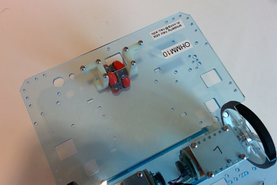
- Get your toolkit, two drive motors, one bottom plate, 8 4-40x3/8" screws, and 8 4-40 locknuts.
- Orient the plate as shown.
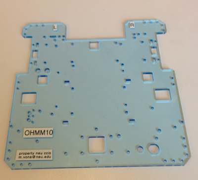
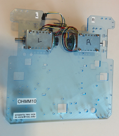
- Assemble the motors to the underside of the plate with screws going down through the plates with locknuts on the underside. One side of each locknut has a white plastic insert—the other side of the nut screws on first. Make sure to mount the motor labeled “L” on the robot’s left side, and the one labeled “R” on the robot’s right side.
- wheels, hubs, and jackstand
- Get two two drive wheels with hubs (they are identical) and a jackstand. Make sure they each have two setscrews. Look into the drive shaft mounting hole on each wheel and make sure the setscrews are not protruding into the hole yet.
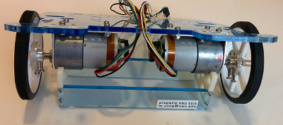
- Push one wheel all the way onto one of the motor drive shafts, as far as it will go. The hub goes on first. Align the setscrews with the flat on the shaft (this is important, do not tighten the setscrews unless they are aligned to the flat because otherwise they will make indentations on the shaft and that will make it hard to dissassemble). Tighten the setscrews firmly. Repeat with the other wheel.
- Feed the motor and encoder leads up through the front central square hole in the lower plate.
- Examine how the jackstand fits under the drive motors. The robot must be on this stand anytime you run the motors while it is not on the floor.
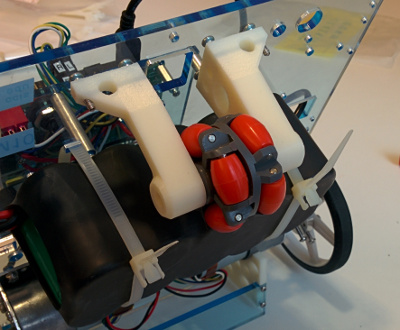
- rear omni wheel
- Get one omni wheel, one rear wheel axle, one left and one right rear wheel bracket (they are mirror images of each other), and 6 4-40x5/8" screws.
- Push the brackets and wheel onto the axle.
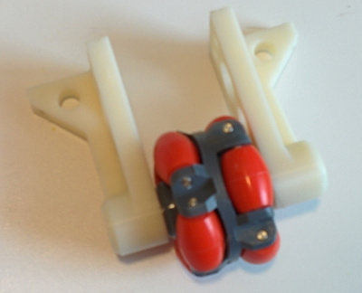
- Line up the mounting holes underneath the bottom plate and assemble from above with 6 4-40x5/8" screws.
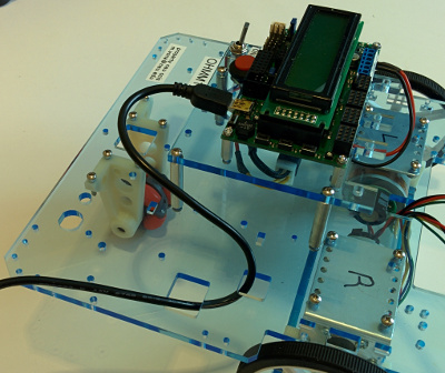
- electronics stack
- Get one long USB A to mini-B cable,your electronics stack (also numbered), four 4-40x3/8" screws, and one small ziptie.
- Screw your electronics stack to the bottom plate with the 4-40x3/8" screws. The correct mounting holes are the two just inside the rear battery ziptie slots and the two just behind the motor mounts.
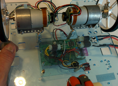
- Feed the smaller connector on the long USB cable down through one of the square holes on the right side of the top plate, then back up through another. Leave an inch or two of slack and then plug it into the org. Eventually your robot will be driving around and the cable will get pulled — by looping it through the holes the load will go into the top plate, not the delicate connector.
- Carefully feed the motor encoder cables under the org board and attach them in the rear of the board in the positions labelled
L and R.
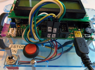
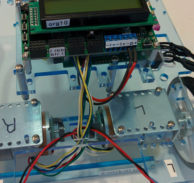
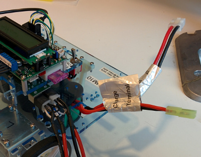
- Carefully attach the left and right motor power wires (black=
-, red=+) to the labelled screw terminals on the front of the org board. The left motor terminals are labelled -l+ and the right motor terminals are labelled -r+. It is very important to connect these wires correctly—trace them back to the left and right motors to be sure you got it right.
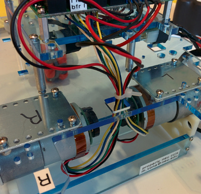
- Put the small ziptie around all the motor wires just above the bottom plate. Cut off the extra with the cutter on your pliers.
- battery
- Get two large zipties, your battery and charger (they are numbered).
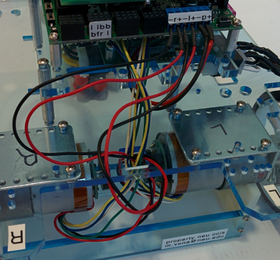
- Orient your battery with the leads on the top side and facing to the robot’s left side. Strap your battery under the bottom deck with two zipties. The zipties are finnicky and should be oriented as shown.
- Feed the battery leads up through the large square hole on the left side. Don’t attach them to anything until instructed.
- final inspection
- Have your assembly inspected by the course staff.
- Connect the battery and power up!
Please read about battery charging and safety here.
These instructions assume you have already configured your machine and made SVN checkouts as described in lab 0.
- In
robotics/ohmm-sw/llp/mottest run make to build the motor test program.
- put your robot up on its stand — we do not want it driving off the table.
- Follow the instructions in lab to turn your robot on.
- Upload the mottest program to the org. (
make program)
- Use the mottest program to test that your motors are rotatating in the correct directions, and that the encoders are reading correctly.
- The encoder counts are shown at the right on the LCD. Verify that the upper count increases when you manually rotate the left wheel as it would rotate when the robot drives forward (i.e., clockwise as you face the outside of the wheel). Do the same for the right wheel, the only difference being that its count is the lower one.
- Press the middle button to send the PWM command listed as “speed” to the motors. They should both start turning as they would to make the robot drive forward.
Be careful when the drive wheels are turning. They can be surprisingly strong and fast. Keep fingers, hair, and dangling clothing away from the spinning wheels and the motor backshafts (with the encoder discs).
These instructions assume you have already configured your machine and made SVN checkouts as described in lab 0.
Follow similar instructions to copy the lab 1 framework as for lab 0, but change l0 to l1 in the instructions (do not delete your old l0 directory).
Please do not edit the provided files, in part because we may need to post updates to them. Any edits you make in them will be overwritten if/when you re-copy them to get our updates. You will need to modify the provided main.c file, at least to include one or more .h files and some function calls to your own code, as described below. By limiting your edits to main.c to just these lines, you will have an easier time if we need to distribute a new version of main.c.
- In
robotics/ohmm-sw/llp/monitor run make lib to build the OHMM monitor library libohmm.a. This is a library of C functions that we have developed to run on the org and to manage many of the robot’s functions. In this lab you will be adding functions to the monitor, but it already includes many built-in functions that you should get to know first. You only need to re-run this make command if we update the provided monitor library code (which we will do at least once, to distribute the solution code for this lab).
Then in robotics/gN/l1 run
> make
> make program
to build the monitor executable ohmm.hex and to upload it to the org. This tacks on an entry point (the main() function) to the monitor library code. The entry point calls some of the library functions to start it up.- Use minicom or kermit to connect to the org USB_COMM serial port, which should appear on your Linux host as
/dev/ttyACM1. See the comments in robotics/ohmm-sw/llp/monitor/minirc.acm1 and robotics/ohmm-sw/llp/monitor/kermit.scr for details. Once minicom or kermit is connected, reset the org and you should see a banner and prompt. Follow the instructions to get a command list. Explore the commands. Make sure your robot is up on a jackstand if you try any of the motor commands.
Use your editor to study the sourcecode for the OHMM monitor library. Read the documentation for each module in robotics/ohmm-sw/llp/monitor/ohmm/*.h. There is both general documentation at the top of the file and documentation for each public macro and function further down. Also (possibly first) read the entry point code in robotics/gN/l1/main.c.
As you develop your code for this lab, please create one or more new foo.c files in robotics/gN/l1 and write your code there. Each should also have a matching foo.h file which is included both in the foo.c file and in main.c (use the syntax #include "foo.h", i.e. use double quotes, not angle brackets).
The makefile should not need to be modified: it is pre-configured to find the Pololu AVR Library (installed in a system location) and the OHMM monitor library in ../../ohmm-sw/llp/monitor. It also will automatically compile and link all .c files you create in robotics/gN/l1.
- Study carefully the
cmd module in the monitor, and how monitor shell commands are registered and implemented in the other modules.
Implement a new monitor command dgvw (drive get
 ) which takes no arguments and which returns two floating point numbers. The first return is the current robot forward velocity
 in mm/sec and the second is the current CCW angular velocity
 in rad/sec. These should be calculated from the results of
 motGetVel() using the velocity FK transformation. You will also need to supply the wheel radius
 and baseline
 (distance between the wheel contact points on the ground). You can either add monitor commands to set/get these interactively (start them out with reasonable hardcoded defaults), or just use
 #define constants.
If you study the code carefully, you may notice that we use fixed point math internally in the mot module; you should not need to do this. Just use float math as you usually would. It will work but you should realize that all floating point operations are implemented by avr-gcc as software subroutines, and as such will be much slower than integer operations. There should be plenty of cycles in this context.
You may find the HLP_DBG() macro in the hlp module helpful. Search through the provided monitor code for some examples of its use (you may also find the script find-in-c-source.sh handy).
Implement a new monitor command dsvw (drive set
) which takes two floating point arguments,
and
in the same units as above, and which makes a corresponding call to motSetVelCmd() after applying the velocity IK transformation.
Implement a new monitor command dsvl (drive set
 ) which takes two floating point arguments
and
) which takes two floating point arguments
and
 .
is the forward speed command in mm/s as above.
is the desired turning radius in mm. Figure out the transformation from
to
and then continue with a call to your
handling code. Please make the
arguments have the same semantics as the two arguments to the iRobot Create
.
is the forward speed command in mm/s as above.
is the desired turning radius in mm. Figure out the transformation from
to
and then continue with a call to your
handling code. Please make the
arguments have the same semantics as the two arguments to the iRobot Create drive command, which is documented on page 9 of the Create Open Interface v2. The special cases specified for the Create with
 should be respected. Note that in the standard two’s complement binary representation
 ,
,
 (there appears to be a missing minus sign before 32768 in the iRobot document), and
 where the
 values are in hexadecimal. Please treat the additional special case
 the same as case
 .
.
Implement a new monitor foreground task that implements incremental odometry as developed in Lecture 3. Register the task to run at 20Hz. Assume the robot pose starts at
 , i.e. aligned to world frame. Use units of mm for
 and radians for
 . Each time the task runs, use
 motGetPos() to get the new wheel rotation amounts, subtract their values from the last update, then update
 accordingly.
Implement a new monitor command dgp (drive get pose) that returns the most recently calculated
 as three floating point numbers. Note that you will not need to worry about the handler for this command running concurrently with the periodic odometry update task — they are both run in the foreground, and foreground tasks never interrupt each other.
Implement a new monitor command drp (drive reset pose) that resets
 .
.
Implement a new monitor command df (drive forward) that takes one floating point argument: the number of millimeters to drive forward (or backward, if negative). Upon receipt of the first df command, the robot should start moving in the indicated direction. One option is to hardcode a reasonable travel speed, say 100mm/s. Another option is to implement trapezoid velocity profiling as explained in lecture 4.
The command handler must not block while the motion completes, but instead should register a periodic task to check for completion, and then return quickly so that other foreground tasks can run. You can also modify your odometry task so that it additionally checks for completion of the current drive command. Of course, the desired position will not exactly be reached; you will need to define a reasonable tolerance interval within which the drive is considered complete.
If another df command is received while one is ongoing, the new command should be queued. Implement a queue that can store up to at least 32 drive commands. (You may wish to study the code in the task and cmd modules which uses arrays of structs to store other kinds of data.) When a drive command completes, the next one, if any, should be popped off the queue and begin execution.
Implement a new monitor command dgs (drive get status) that returns one int, which the number of commands currently waiting in the drive command queue, if any, plus one if a command is currently executing. Thus, dgs should return zero iff (if and only if) no command is executing and none are queued.
Implement a new monitor command dp (drive pause) that pauses the current drive command, if any. Also implement a companion command dup (drive unpause) that resumes driving if paused. Make sure you can run these commands even if the queue is empty. If a df or dt command is issued while a pause is in effect then the command should still be added to the queue (as long as the queue is not full). That way you can enqueue a “batch” of commands before the robot starts to move.
Implement a new monitor command dri (drive reinit) that stops any ongoing drive command, if any, and then drops it and any other queued drive commands.
Implement a new monitor command dt (drive turn) that takes one floating point argument: a turn-in-place angle in CCW radians. The execution semantics of dt should parallel those of df. Note that there should be a single queue for both the df and dt commands, so that you can queue up a mix of commands to drive in e.g. a 500mm square. We provided a file drive-square-500mm.txt in g0/l1 containing such a sequence. See sequences-howto.txt in the same directory for instructions on how to upload it using minicom.
Devise two experiments: one to help you calibrate your estimated value for the wheel radius
, and another to help you calibrate the estimated value for the baseline
. Use these to try to optimize the accuracy of drive sequences. For example, try driving in a square or triangle pattern where the robot should ideally return to its original pose. (The calibration experiments should actually be simpler, e.g. just one df for the
calibration and one dt for the
calibration.)
You will be asked to demonstrate your code for the course staff in lab on the due date for this assignment (listed at the top of this page); 30% of your grade for the lab will be based on the observed behavior. Mainly want to see that your code works and is as bug-free as possible. To a much lesser extent, we will also consider the accuracy of your odometry and drive sequences. We will not consider the robot speed as long as it is not absurdly slow (e.g. it should be able to drive a 1m square pattern in no more than ~2 minutes).
The remaining 70% of your grade will be based on your code, which you will hand in following the general handin instructions by the due date and time listed at the top of this page. We will consider the code completeness, lack of bugs, architecture and organization, documentation, syntactic style, and efficiency, in that order of priority. You must also clearly document, both in your README and in code comments, the contributions of each group member.
