Due Wednesday Mar 12, 11pm
Worth: 9% of your final grade
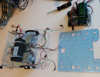
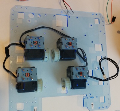
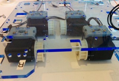
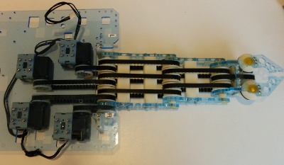
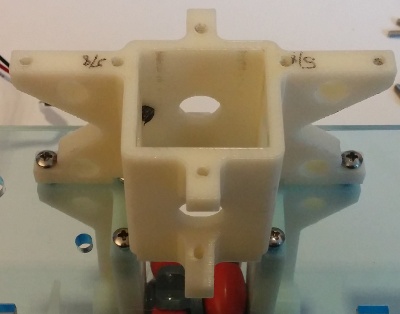
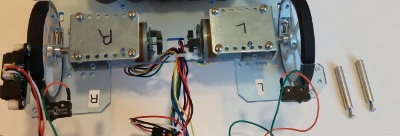
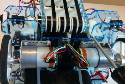
In the first part of this lab you’ll attach a manipulator arm to your robot. This arm has three rotating joints and a gripper, all actuated by Robotis AX12 “Dynamixel” robot servos (doc). These receive battery power via the LLP and are controlled by a serial communications interface also on the LLP. Monitor commands are provided (and their Java and Scheme correspondents) to move the arm and to query its state.
In the second part of the lab you’ll write high level code on the HLP to move the gripper to commanded
![]() locations in world frame, using the robot’s turn-in-place capability to add a fourth rotating degree-of-freedom (DoF) to the arm workspace. In the third part you will program the robot to drive towards the location of a known object on the ground, deploy the arm, and grasp the object.
locations in world frame, using the robot’s turn-in-place capability to add a fourth rotating degree-of-freedom (DoF) to the arm workspace. In the third part you will program the robot to drive towards the location of a known object on the ground, deploy the arm, and grasp the object.

Follow similar instructions as for lab 2 to update your svn checkout and copy the lab 3 framework into robotics/gN/l3.
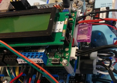
Then rebuild and flash the LLP monitor code using the same procedure as for lab 2.
Finally, rebuild the HLP OHMM jarfile using the same procedure as for lab 2.
The monitor program includes a set of ax* commands to interact directly with the AX12 servos (documented in robotics/llp/monitor/ohmm/ax12.h). It also includes a set of a* commands to interact with the servos in the context of the manipulator arm (documented in robotics/llp/monitor/ohmm/arm.h). It is strongly recommended to use only these higher-level arm commands except for debugging and calibration purposes.
The Java OHMM library and the Scheme OHMMShell also provide access to all these commands.
The notes for Lecture 9 give details of the arm kinematics, including the link lengths. They also present an analytic IK approach for this arm.
Bring up OHMMShell or use a serial terminal program like minicom to talk directly to the OHMM monitor program running on the LLP. Then run the following commands to enable the arm and send it to the calibration pose:
OHMMShell
> (ae #t)
> (ac)

minicom
> ae 1
> ac
The calibration pose is intended to have the arm pointing straight forward with the gripper closed. This pose should be reached by setting each servo to the goal position 512 in AX12 counts (the AX12 servos have a range of motion of 0 to 300 degrees, with 0 degrees corresponding to 0 counts and 300 degrees corresponding to 1023 counts, so 512 counts corresponds to 150 degrees, with the servo at the midpoint of its range of motion). However, various sources of error will cause each arm to reach a slightly different pose when all servos are commanded to 512.
Very carefully using commands like
OHMMShell
> (axsg I C)

minicom
> axsg I C
where I is a servo index (0 = shoulder, 1 = elbow, 2 = wrist, 3 = gripper) and C is the goal counts (start with 512 and work in increments of about +/- 10 counts at a time), try to adjust your arm so that it appears to be in the correct straight-forward calibration pose.
You may also judiciously tension the gripper to close with a little bit of force during this process. Try adding and subtracting 10 counts from the gripper servo 3 first to understand which direction closes and which direction opens the gripper. Then open the gripper to a small gap, followed by closing it in small increments until the fingers are just touching. Continue closing by 10 or 20 further counts to tension the gripper a bit. (Note: the gripper state actually is set by the difference between servos 2 and 3, so you may also need to fiddle with servo 2 to maintain the calibration pose.)
Once you are satisfied with the calibration, “freeze” the current targets of each servo as the new calibration:
OHMMShell
> (afac)
> (agac #f)

minicom
> afac
> agac s
Write down the four calibration values, you will need them if you later re-flash the LLP. The arm should not move when you do this, but if you then test the calibration by running
OHMMShell
> (ah)
> (ac)

minicom
> ah
> ac
the arm should move to the home pose when you run ah and then back to the calibration pose when you run ac. The calibration values will be stored on the LLP in nonvolatile EEPROM so so that you should not have to re-calibrate unless you re-flash the LLP (in which case the EEPROM will be erased).
If you ever want to reflash the LLP, you can first read out the arm calibration data stored in the EEPROM by running
OHMMShell
> (agac #f)

minicom
> agac s
Then write it down, do the reflash, and then reset the calibration values to EEPROM with
OHMMShell
> (asac C C C C)

minicom
> asac C C C CUsing the inverse kinematics method of your choice, implement a program that runs on the HLP (this is a requirement), homes the arm, and then responds to keypresses as follows, with step distance
![]() initially:
initially:
w — move the gripper +
![]() mm in the world-frame
mm in the world-frame
![]() direction
direction
s — move the gripper -
![]() mm in the world-frame
mm in the world-frame
![]() direction
direction
a — move the gripper +
![]() mm in the world-frame
mm in the world-frame
![]() direction
direction
d — move the gripper -
![]() mm in the world-frame
mm in the world-frame
![]() direction
direction
r — move the gripper +
![]() mm in the world-frame
mm in the world-frame
![]() direction
direction
f — move the gripper -
![]() mm in the world-frame
mm in the world-frame
![]() direction
direction
q —
![]() z —
z —
![]()
Assume that the robot is at world frame pose
![]() initially.
initially.
To enable
![]() direction motions use turn-in-place drives to add a “yaw” DoF to the arm kinematics. You may want to use the
direction motions use turn-in-place drives to add a “yaw” DoF to the arm kinematics. You may want to use the dos monitor command, part of the solution code for the drive module documented in robotics/ohmm-sw-site/llp/monitor/ohmm/drive.h as driveOrientationServo(float). This is available at the java level as OHMMDrive.driveOrientationServo(float) and in scheme as (dos <float>). The dos command is not queued like df and dt. You can check whether the robot has already reached the desired orientation by repetitively running dos with the same target angle; the return will be nonzero (true) until the angle has been reached to within a tolerance band.
Use the wrist joint to keep the gripper horizontal (parallel to the ground, as it is in arm home pose) at all times.
If the target location is not reachable, your program must emit a message. However, it is up to you to decide how to move the arm in the case of unreachable targets. For example, you could make a best-effort motion to reach towards the target. However you do it, you must maintain the following property: any sequence of keypresses followed by the reverse sequence, e.g. “wwrrffss”, must return the arm to the home pose. This should hold even if the arm target is unreachable at any time during the sequence.
You may find that reading a single keypress from the console is not easy in Java; in fact, technically, it’s not possible to do in a portable way using the current standard Java API. However, here we will accept a solution which runs on Unix; for that see the provided code in ohmm.ConsoleNonblocking. Alternatively, we will accept solutions which open a graphics window and then respond to KeyEvents there.
Retrieving objects on the ground is a common task in mobile manipulation. In this part, you will implement a basic method to approach an object, grasp it, and carry it. The manipulation “lollipop” object is tall enough so that the gripper can engage it when lowered to within a few centimeters of ground clearance.
Using your horizontal-gripper IK solution from above, write a program to produce a yaw-free grasp sequence starting from home pose:
The robot chassis should remain in place at all times. Note that the interpolations must approximate straight-line motions in space. It will not work to go directly to the joint angles at the ends of the interpolations; you need to generate intermediate waypoints along the interpolation lines at some rate and use inverse kinematics to convert each of those waypoints into intermediate joint angles.
Calculate the robot frame
![]() offset distance
offset distance
![]() from the robot frame origin where an object on the ground should be grippable at step d. Practice picking up the object specifically placed at robot frame coordinates
from the robot frame origin where an object on the ground should be grippable at step d. Practice picking up the object specifically placed at robot frame coordinates
![]() using the whole sequence of motions above. Tune the sequence as you see fit to maximize grip success.
using the whole sequence of motions above. Tune the sequence as you see fit to maximize grip success.
Extend your program so that it can take the
![]() coordinates of the object on the ground as command line arguments in world frame millimeters (if no command line arguments are given, then the program should revert to keyboard control inverse kinematics as above). For example, if your Java class to solve this part is called Grasp, you should be able to invoke it like this
coordinates of the object on the ground as command line arguments in world frame millimeters (if no command line arguments are given, then the program should revert to keyboard control inverse kinematics as above). For example, if your Java class to solve this part is called Grasp, you should be able to invoke it like this
> ./run-class Grasp 30 40for a goal at
![]() mm in world frame. Assuming the robot starts at pose
mm in world frame. Assuming the robot starts at pose
![]() in world frame, have your program
in world frame, have your program
Note: you may need to re-calibrate the robot wheel-to-wheel baseline distance to improve the accuracy of turn-in-place motions. You may optionally take a third command line parameter giving the robot baseline distance in mm (thus allowing it to be adjusted at the beginning of each run).
You will be asked to demonstrate your code for the course staff in lab on the due date for this assignment (listed at the top of this page); 30% of your grade for the lab will be based on the observed behavior. Mainly want to see that your code works and is as bug-free as possible.
The remaining 70% of your grade will be based on your code, which you will hand in following the general handin instructions by the due date and time listed at the top of this page. We will consider the code completeness, lack of bugs, architecture and organization, documentation, syntactic style, and efficiency, in that order of priority. You must also clearly document, both in your README and in code comments, the contributions of each group member.
