Computer Graphics (CS 4300) 2010S: Lecture 21
Today
- introduction to ray tracing
- discuss HW6
Ray Tracing
- we now begin to study a somewhat different way to produce renderings of 3D scenes, called ray tracing
- unlike the rasterization process we have studied till now, it will be relatively easy to handle not only depth occlusion, perspective projection, and diffuse and specular shading, but also reflections, shadows, and refractions
- the following image shows a typical ray-traced rendering of a scene with three reflective spheres, a checkered plane, and various light sources (image credit: Craig Oatley)
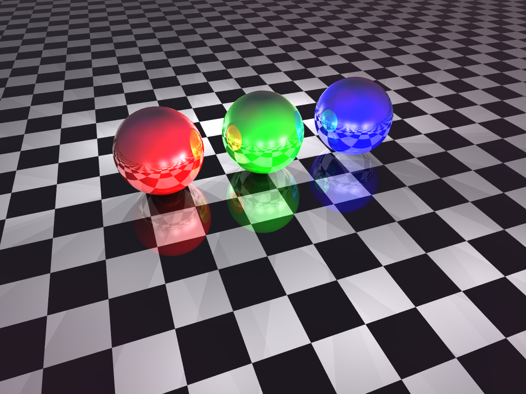
- these effects, as well as others, are more easily implemented than in rasterization because the approach of ray tracing more closely models the actual interaction of light with surfaces in the 3D scene
- the difference is not in the lighting model, or even in the shading equations
- i.e. the standard point, directional, spot, and ambient lights, as well as the Lambertian (diffuse) and Blinn-Phong (specular) shading equations we studied in L20, can be used in ray tracing just as they are used in rasterization
- rather, ray tracing makes a more complete model of the path of light rays between light sources and the image plane of the camera
- we are careful not to say “from” light sources “to” the camera, because the key insight of ray tracing is that it is possible, and a much smaller computational problem, to trace the rays in exactly the opposite direction
- in ray tracing we trace the reverse path of light, starting from the eye point, and ending at light sources
- why is this more efficient?
- in fact it is possible to trace the forward path of rays from light sources
- in reality there are an infinity of such rays emanating from each source
- even if we just sample a large number of them, for most scenes, most rays bounce around but never hit the camera
- people do sometimes implement this, which can be called the radiosity method
- clearly we would like to somehow be able to just trace the rays that actually hit the camera (perhaps after some reflections), since the others cannot affect the image anyway
- the setup of perspective projection, with all rays going through the image plane and converging on an eye point behind it, means that for each pixel it is reasonable to just consider one ray for that pixel
- i.e. the ray
 that goes through the point corresponding to that pixel in the image plane, and also through the eye point
 - (the math is only slightly different for parallel projection)
- if we trace
 into the scene, it may hit an object surface at an intersection point
- it may hit nothing; if so just set that pixel a “background” color
- if it does hit something, color the pixel according to the shade of the first surface that is hit
- this is exactly the same intersection process as we have already discussed for 3D picking; it can also be accelerated using bounding volumes
- the pixel color
 can be calculated by applying the lighting model and shading equations we studied in L20
 - but we can easily take the process further, and continue tracing back through the scene
- to implement shadows from a light source, check the ray
 from the intersection point
  towards the light source
- if it hits another surface first, that light source is shadowed at

- to implement mirror reflections that are much more realistic than Blinn-Phong specular highlights, compute the mirror reflection
 (details later) of the ray from the eyepoint at
  , and recur
- i.e. see if
 hits some other surface
 - if so, calculate its shaded color
 using exactly the same procedure (possibly including a further reflection)
 - and then add that to the shaded color at

- typically the specular color of the current surface is used to modulate (and effectively attenuate)
 , so the usual math to incorporate the reflection is
  , where
  is the specular color of the surface and
  is the element-by-element multiplication we introduced in L20
 - in practice, each level of reflection adds additional computational cost, but with diminishing effect (because of the compounded attenuation)
- also, there can easily be rays that bounce around forever (or for a very long time)
- thus, the number of chained reflections, or the recursion depth of the mirror reflection calculation, is typically limited
- overall, another way to view the difference between ray tracing and rasterization is to consider both to process both canvas pixels and object surfaces
- for rasterization, also called object-order rendering, we primarily iterate over all the object surfaces, and then in an inner loop consider all the affected screen pixels
- for ray tracing, also called image-order rendering, we primarily iterate over each screen pixel, and then in an inner loop find all object surfaces that affect it
Computation Cost
- for a scene with
 object surfaces and
  lights and a canvas with
  pixels, what is the worst-case running time of object-order rendering (rasterization)?
- answer:
 , because each primitive could cover the whole canvas in the worst case (
 fragments for every primitive), and we have to consider the effect of each light on each fragment
- how about for image-order rendering (ray tracing)?
- answer: if the maximum recursion depth of mirror reflection is
 , then ray tracing is
  because for each pixel up to
  rays will have to be intersected with all
  surfaces
Calculating Reflections and Refractions
- when a light ray hits a surface, we may want to calculate up to two derived rays
- the ray that would be reflected according to the mirror reflection law
- the ray that would be refracted according to Snell’s law, if the surface is the boundary of a translucent material (another word for a translucent material is “dielectric”)
- recall that we have defined the following unit vectors to study the local interaction of light at a surface point
 :
: is the outward pointing surface normal
 is a unit vector towards the viewer (we will generalize in this discussion to make
  point towards the source of the incoming ray; that will be towards the viewer for a primary ray, or towards the last intersection for a reflection ray)
 is a unit vector towards a light source, which we will not need here
- to calculate
 , a unit vector in the mirror reflection direction of
  , observe that if we place a copy of
  so that its tail is at
  and then reflect about the surface we get
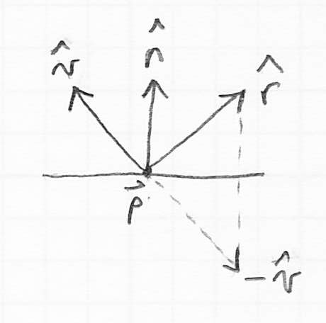
- how to compute the reflection?
- observe that
 can be decomposed into a component parallel to the surface and a component perpendicular to the surface:

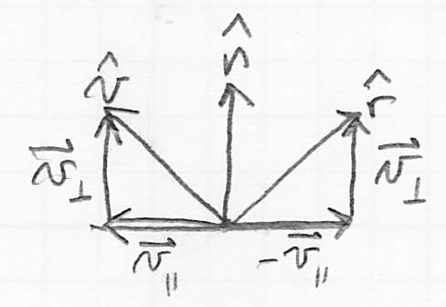
- then
 and
and 
- now the reflection can be calculated as

- to calculate
 , a unit vector in the direction of the light transmitted into a translucent material, we use Snell’s law instead of the mirror reflection law
- let
 be the index of refraction of the source material, and
  be the index of refraction of the destination material
 - the index of refraction is a scalar constant that is related to the speed of light through a given material
- the index of refraction of air is close to 1; water is about 1.3; glass is about 1.5
- light rays change direction when they cross a boundary where

- we can quantify this by defining
 , the angle between
  and
and  , and
, and  , the angle between
  and
and  (i.e. the inward-pointing surface normal)
 - Snell’s law states that

- so
 implies
  , and vice-versa
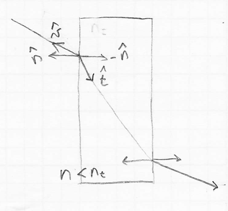
 can be worked out from this relationship (derivation in the course text, Shirley and Marschner 3rd ed. p. 304)
- (it can be shown that
 is in fact a unit vector)
 can be derived from
  using the trig identity


- the case where the quantity under the square root is negative turns out to be equivalent to total internal reflection where the light ray bends so much that it actually does not enter the surface—i.e. the surface acts like a pure mirror, and there is no refracted ray, only a reflection
 as calculated above
Instancing
- we can easily define a model within a scene and then make multiple copies of that model, each transformed by its own local-to-world transformation matrix, also called a composite model transform or CMT

- it can be most efficient to not transform the object itself, but rather transform all light rays that interact with the object by

Constructive Solid Geometry
- constructive solid geometry, or CSG, is yet another seemingly complex feature that turns out to be relatively easy to implement in the context of ray tracing
- the idea of CSG is that we can construct a new solid object from two starting pieces
 and
and 
- for example
 could be a sphere and
  could be a cube
- but a CSG system must handle the case of
 and
and  being any solid shapes
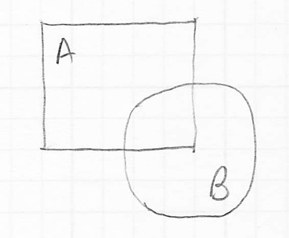
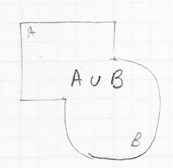
- one thing we can do is ask for the union
 , which means that
  is a new solid shape that contains all the points in
  plus all the points in
- this is mainly interesting for the case where
 and
and  start out overlapping
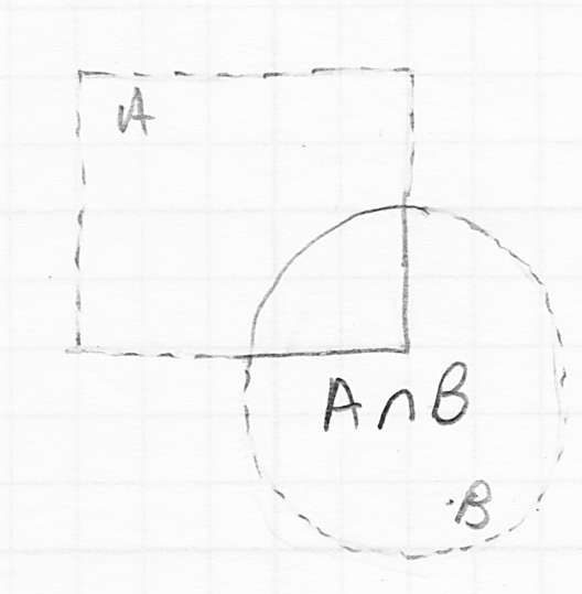
- a second operation is to take the intersection
 , which means
  contains only the points that were originally in both
  and
and 
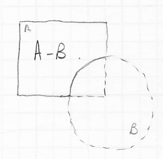
- finally, we can take the differences
 or
or  (in general these give different results
- e.g.
 means take any point that was originally in
  as long as it was not also originally in
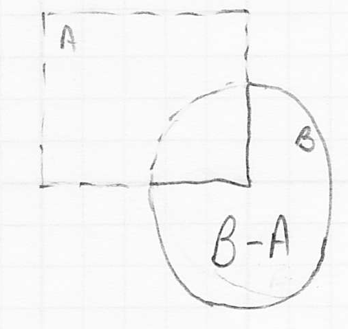
- given a set of such boolean operations, we can cascade them
- for example starting with solids
 ,
,  , and
, and  , we could compute
- in general we can make an arbitrary tree of CSG operations
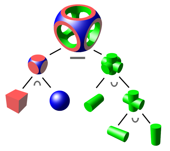
(image credit Wikipedia)
- how to implement CSG?
- one possibility would be to actually make new models
- if
 and
and  were originally closed-surface triangle meshes, it is possible to build a CSG algorithm that will compute the above four operations and generate a new closed-surface triangle mesh
- this has been done, and is useful, particularly in CAD programs, but it’s tricky to get it right
 may end up with multiple disconnected components
- if
 and
and  were just barely touching then
  may not actually be a 3D volume, but only a 2D (surface), 1D (curve), or 0D (point) object
 - in fact, different components of
 could have different dimension
- if we only care about rendering an image as it would appear if the CSG operations were to have taken place, then in the context of ray tracing there is an easier approach
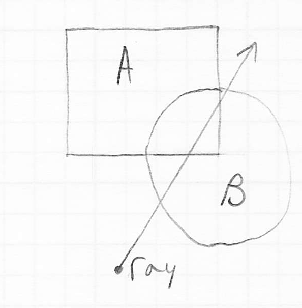
- consider a ray that hits a pair of solid objects
 and
and  upon which a CSG boolean operation has been applied to produce a result
- the ray tracer must behave as if
 and
and  were not in the scene, but replaced by
- the key insight is that the boolean operation can be equivalently performed on just the 1D intervals corresponding to the containment of the ray inside
 and
and 
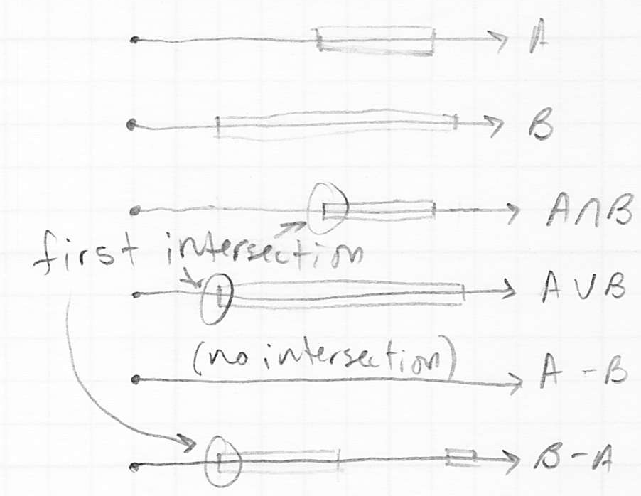
- these 1D intervals can be easily computed by finding all intersections (not just the nearest) of the ray with each object
- then the specified boolean operation can be applied to the two resulting sets of intervals, producing a third set of 1D intervals
- that latter set, call it
 , gives precisely the intervals that would would have been included along the ray if it were to have intersected the volume
- thus we can answer the question that we need in ray tracing, which is to find the nearest intersection of the ray with
 : this is just the start of the first interval in
Antialiasing, Soft Shadows, and Blurred Reflections
- standard ray tracing produces beautiful images, but often they are so “clean” that they appear unnatural
- reflections are perfect, as if all surfaces were perfectly clean and smooth
- shadows have hard edges, not the graded transition from umbra to penumbra that we usually see in reality
- also, just as with rasterization, if we sample each pixel with only one ray, we get aliasing effects, which make edges in the scene appear jagged
- all of these issues can be addressed by variations on a technique called distribution ray tracing
- the basic idea is to replace tracing a single ray by tracing along a set of random rays nearby the original
- this is most directly obvious for the case of anti-aliasing
- originally, we just shot a ray through the center of each pixel
- now we generate a set of rays that go through different parts of the pixel, and average the result
- we can use a regular pattern of sub-pixels (say 4x4), but this again can result in noticeable artifacts, including moiré patterns
- instead we randomize the rays
- that itself can introduce some objectionable effects, so we balance the two by randomizing the rays but keeping them within the sub-pixels
- of course, this all slows down the ray tracing process significantly: using 4x4 sub-pixels means that instead of tracing one ray per pixel, we need to trace 16!
- soft shadows are another effect that can be easily implemented at the cost of shooting many more rays
- the shadows we have computed so far have hard edges because we have always considered the visibility of a light source from a point on a surface to be a boolean value: the light is either visible (not shaded), or it’s not visible (shaded)
- in reality, this is not what actually happens, because real light sources are not ideal points or ideal directions
- what really happens is that there is some surface (like the globe of a lightbulb) that is emitting light
- geometrically, this light-emitting surface could be
- entirely hidden by some intervening object, producing the darkest part of the shadow, or the umbra
- partly hidden by an object, producing an intermediately dark shadow, called a penumbra
- not at all hidden by an object (no shadow)
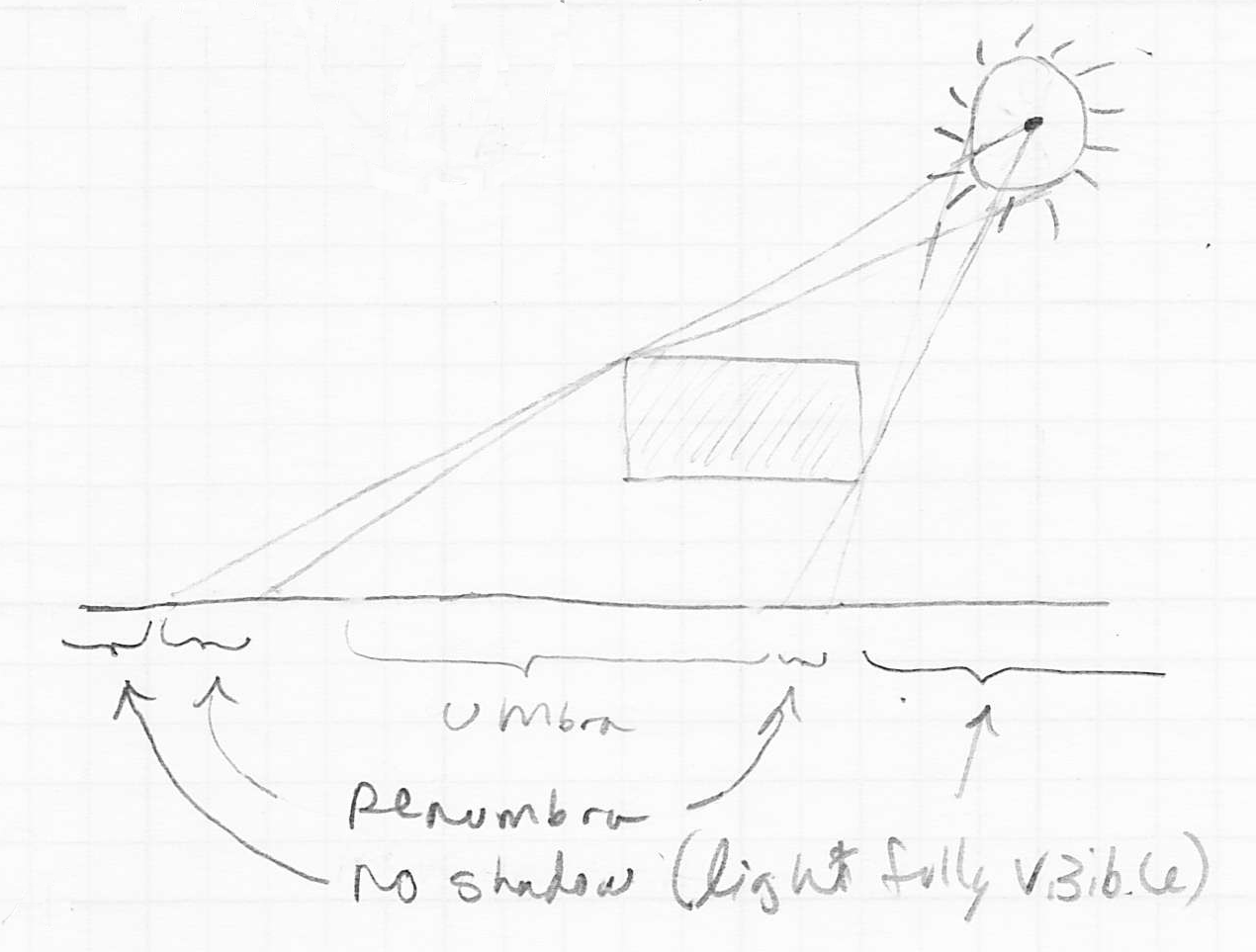
- so far we only calculate the umbra
- we do that by shooting one ray from the surface point
 towards the light source
 - this is sufficient for a true point or directional source, because there is only one possible ray from
 towards the light in those cases
 - but if the light is itself a surface with some extent, there are in reality an infinity of rays that go from
 towards the light
 - we cannot trace an infinite number of rays, but we can take a random sampling of rays from
 to the light surface
- the fraction of them that intersect some intervening object then gives the degree of shadow of
 with respect to that light source
 - the more we use, the more accurately we can estimate the degree of shadow
- another very similar technique can be applied to simulate the blurred reflections that occur in reality
- so far we can compute mirror reflections, but these look very “clean”, because we treat the reflecting surface as free of any imperfections
- very few real surfaces are so perfect
- so even surfaces that produce noticeable reflections add some blur
- microscopically, this is partly because the surface has small bumps, which perturb the reflected rays away from the ideal direction given by the mirror law
- you can probably guess how we can do something similar: instead of computing the exact mirror reflection vector
 , as above, we can randomly perturb it by a small angular amount
 - fortunately, this is one effect that does not involve adding more rays
Next Time

 that goes through the point corresponding to that pixel in the image plane, and also through the eye point
 into the scene, it may hit an object surface at an intersection point
 from the intersection point
  towards the light source
 (details later) of the ray from the eyepoint at
  , and recur
 hits some other surface
 using exactly the same procedure (possibly including a further reflection)
 , so the usual math to incorporate the reflection is
  , where
  is the specular color of the surface and
  is the element-by-element multiplication we introduced in L20


