Assignment 10: LightEmAll
Goals: Design a game with mutable world state, ArrayLists, and loops. Practice working with graphs and graph algorithms by using Kruskal’s algorithm. Gain more practice using the Impworld library.
Implementation and Submission Requirements
Once again, you will be using the Impworld library, as in Assignment 9 —
make sure that at the top of your file, you include import java.util.ArrayList; import tester.*; import javalib.impworld.*; import java.awt.Color; import javalib.worldimages.*; Make sure you do not name any of your files World.java, or else handins will not be able to compile your code.
You will submit this project twice. Each time, you will submit all the files needed for your game, in one .zip file.
Instructions
This assignment is long. Start early.
You will submit this project twice, first with a basic board generation design, then with a board generated using Kruskal’s algorithm, which you will cover in class in the interim. This section outlines the high-level task descriptions for the two parts. It will serve as a kind of checklist at the top of the project description that you can easily refer to as you work on it. (It is not meant to be an introduction, so it will seem confusing the first time you read it, but it will make more sense once you’ve done a pass through this entire document.)
The two submissions will be organized as follows:
Part 1 Due: Thursday April 10th at 9:00pm You must complete the task
of designing and implementing the GamePiece class —
Part 2 Due: Tuesday April 15th at 9:00pm You must design and implement the Edge class. You must design and implement the union/find class for storing Edge sets You must implement Kruskal’s algorithm to generate a more challenging random board. You must submit any additional features or extra credit you attempt.
Extra credit will only count if they are convincingly and thoroughly tested,
and if the rest of the assignment is completed equally thoroughly —
Gameplay
Note: This section describes how your program should work in its final form at the end of Part 2, not what it needs to look like for the intermediate submission.
This assignment is based on a game called Power Line and can be viewed in action here. The main difference is that one of our suggested extra credit options is to design the power station to have some finite radius of effectiveness, which might require the power station to be moved by the player to ensure power reaches every tile.
The board consists of a rectangular grid of tiles, each tile consisting of one to four wires, going from the center of the tile to one or more of the sides. (This leads to 15 different tile configurations if you consider distinct rotations, although that’s more an interesting fact than something you need to explicitly consider in your design.)
The board also has a power station, positioned at the center of one of the tiles.
If the wire from one tile touches the wire from an adjacent tile at the shared side, they are considered connected.
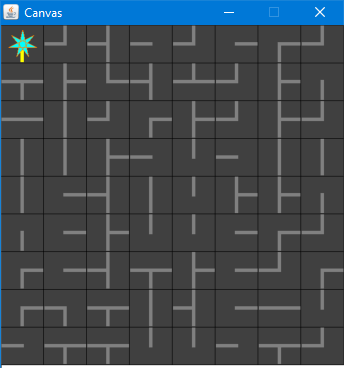
The player’s goal is to light up every tile of the board, by ensuring that all the wires are connected to the power station. Here is an example of an initial board configuration:
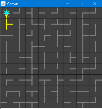
During game play, the player can click on any tile to rotate that tile, reconfiguring how that tile now connects to its neighbors. The player cannot otherwise move tiles:
When the board is first internally generated, it will be constructed in a way that guarantees all the wires on the board are connected. Because some of the tile configurations create branches in the wiring, the connected wiring for the board will form a single connected tree.
The board is then scrambled by randomly rotating each tile, before the game starts. This ensures that a solution is possible through just a series of rotations, effectively undoing the scrambling.
In the extra credit version,
even when the player has managed to connect all of the tiles to the power station,
there is more to the puzzle —
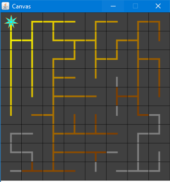
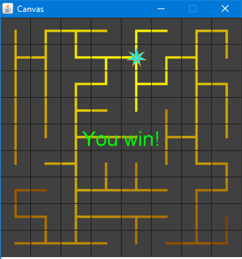
To fix this, the player is allowed to move the power station, by using the arrow keys. Furthermore, the power station can only be moved along the path defined by the wiring. The player wins when all the tiles are lit up, i.e., powered:
10.1 Tasks – Part 1
Here is the list of tasks you will need to complete for the first submission. It will primarily consist of designing the data and methods for the initial board setup, writing code to render the display, as well as allowing the player to rotate the tiles. You will implement the power-up behavior: determining which cells are connected to the power station, and therefore powered, drawing the powered lines and unpowered lines in different colors, and allowing the user to move the power station using the arrow keys. The board generation (i.e., tile wiring layout and power station location) will be a simple manual process.
10.1.1 Setting up the game
Your top-level class, will be called LightEmAll, and will extend the World class, You will need to create a two-dimensional grid of GamePieces to represent the board. The width and height of the board should be specified as arguments to your LightEmAll constructor. Because the size of the board is configurable, you cannot simply hard-code lists of data, but must instead be created using loops and ArrayLists.
class LightEmAll extends World { // a list of columns of GamePieces, // i.e., represents the board in column-major order ArrayList<ArrayList<GamePiece>> board; // a list of all nodes ArrayList<GamePiece> nodes; // a list of edges of the minimum spanning tree ArrayList<Edge> mst; // the width and height of the board int width; int height; // the current location of the power station, // as well as its effective radius int powerRow; int powerCol; int radius; }
Effectively, we have created a graph, where each GamePiece is a node and the wires are edges.
Each GamePiece represents a tile on the board, and has wires extending towards adjacent GamePieces. The boolean fields left, right, top, and bottom indicate which neighboring GamePieces can be connected:
class GamePiece { // in logical coordinates, with the origin // at the top-left corner of the screen int row; int col; // whether this GamePiece is connected to the // adjacent left, right, top, or bottom pieces boolean left; boolean right; boolean top; boolean bottom; // whether the power station is on this piece boolean powerStation; boolean powered; }
For example, the following GamePiece has left, right, and bottom set to true:
A GamePiece may also have a power station, which supplies power to all reachable GamePieces. For Part 1, all you need to do with respect to the power station is design how to display the GamePiece that holds it.
10.1.2 Power station movement
You must implement the ability for the player to move the power station. They will use the arrow keys to move it, so you must add event handlers for these keys. you must also make sure they can only move the power station within the confines of the board. Most importantly, they should only be able to move the station along existing wire connections, so it will depend on how the player has rotated the tiles.
10.1.3 Game end
After each board change by the player, you must check whether all of the cells on the board are connected by wires to the power station, using breadth-first search. If so, the player has won the game, and you should exit with a congratulatory message.
10.1.4 Board generation strategy
Note that the two project submissions will have different board generation strategies, the final one being much more sophisticated.
The specific wiring of the board can be thought of as a “maze”, which is generated by one of two strategies. After this step is complete, the game will shuffle the board, by applying a random number of rotations to each GamePiece.
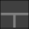
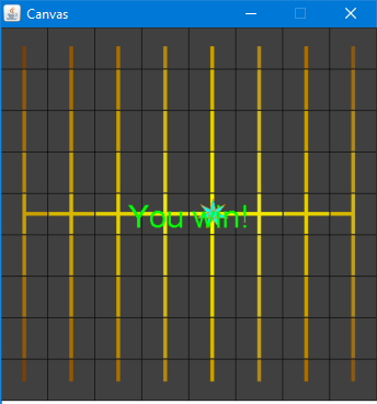
For Part 1, the board will be manually generated, i.e., you will encode a specific board in the game logic, and every game will have the same solution. You should choose a simple pattern, such as all vertical lines with a single, horizontal bar through the center:
Or all horizontal lines with a single, vertical bar through the center:
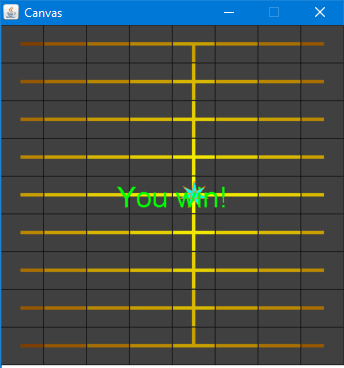
In both of these boards, the initial position of the power station should be at the center.
10.1.5 Rendering the game
GamePiece tiles should be drawn with dark backgrounds. A wire should be yellow when it is powered, and grey when unpowered.
To help you with this part (and to avoid bogging you down in details of how exactly to draw thick wires and fancy power station stars), we are providing the following code, which you should incorporate into your GamePiece class:
class GamePiece { // ... [ Your GamePiece class contents here] // Generate an image of this, the given GamePiece. // - size: the size of the tile, in pixels // - wireWidth: the width of wires, in pixels // - wireColor: the Color to use for rendering wires on this // - hasPowerStation: if true, draws a fancy star on this tile to represent the power station // WorldImage tileImage(int size, int wireWidth, Color wireColor, boolean hasPowerStation) { // Start tile image off as a blue square with a wire-width square in the middle, // to make image "cleaner" (will look strange if tile has no wire, but that can't be) WorldImage image = new OverlayImage( new RectangleImage(wireWidth, wireWidth, OutlineMode.SOLID, wireColor), new RectangleImage(size, size, OutlineMode.SOLID, Color.DARK_GRAY)); WorldImage vWire = new RectangleImage(wireWidth, (size + 1) / 2, OutlineMode.SOLID, wireColor); WorldImage hWire = new RectangleImage((size + 1) / 2, wireWidth, OutlineMode.SOLID, wireColor); if (this.top) { image = new OverlayOffsetAlign(AlignModeX.CENTER, AlignModeY.TOP, vWire, 0, 0, image); } if (this.right) { image = new OverlayOffsetAlign(AlignModeX.RIGHT, AlignModeY.MIDDLE, hWire, 0, 0, image); } if (this.bottom) { image = new OverlayOffsetAlign(AlignModeX.CENTER, AlignModeY.BOTTOM, vWire, 0, 0, image); } if (this.left) { image = new OverlayOffsetAlign(AlignModeX.LEFT, AlignModeY.MIDDLE, hWire, 0, 0, image); } if (hasPowerStation) { image = new OverlayImage( new OverlayImage( new StarImage(size / 3, 7, OutlineMode.OUTLINE, new Color(255, 128, 0)), new StarImage(size / 3, 7, OutlineMode.SOLID, new Color(0, 255, 255))), image); } return image; } }
The provided drawTile() method renders a single GamePiece. It pulls information from the GamePiece to decode what wires to draw, and additional rendering specifications are passed as arguments; for example, what size you want the tile to be drawn. Most importantly, one of the parameters specifies the color to use for the wire, so you can use it to render powered and unpowered wires in different colors. Another parameter specifies whether this tile should have a star drawn on it for the power station.
This image this method returns can be composed using a series of AboveImage() and BesideImage() calls to create the rows and columns of your rendered game board.
For the basic version of the assignment, you do not need to draw wires getting progressively darker as the distance from the power station increases. Implementing this functionality is extra credit.
The power station should be drawn as a star, on top of the wires.
10.2 Tasks – Part 2
Here is the list of tasks you will need to complete for the second, final submission. For this part, you will implement Kruskal’s algorithm to generate a more challenging random board, plus any additional features or extra credit you attempt.
10.2.1 Board generation strategy
For Part 2, you will generate random boards. By treating the wires as edges on a graph and randomly assigning edge weights, you can use Kruskal’s algorithm (see below) to find the minimum spanning tree.
A full detailed description of Kruskal’s algorithm, as well as a description of the union/find algorithm which supports it, is given in the Reference Materials section below.
class Edge { GamePiece fromNode; GamePiece toNode; int weight; }
The power station will initially be at the origin, i.e., the top-left corner.
10.3 Extra credit
You will be allowed to implement the advanced power-up radius feature to earn extra credit for this assignment. Additionally, you will be able to implement other features for even more extra credit, although that will be at the discretion of the instructors.
10.3.1 Power station radius
For this extra credit feature, the power station reach must be modeled as limited by distance, up to an effective radius, where the radius is defined as \((diameter / 2) + 1\). Initially, you will compute the initial radius based on the initial (solved) board, before randomizing it. To compute the diameter of your graph, first run breadth-first search (see below) to determine the last-found GamePiece. Next, run breadth-first search starting from that last-found piece and count the depth to the new last-found piece again. That depth is the diameter of the graph. As long as the board is not fully connected, this initial radius should be used to calculate whether a connected wire is powered or not.
Whenever all the cells are fully connected, you should recompute the power station’s effective radius based on the current configuration. That updated radius should be used to test if all of the cells are within the effective radius of the power station.
10.3.2 Other possible extra credit tasks
If you want to earn extra credit on this assignment, you can complete any number of “whistles” and “bells”. A “whistle” is a fairly small extension to the game; a “bell” is a more elaborate and impressive enhancement. It would take several whistles to be as impressive as a single bell. Whistles and bells are not worth a specific number of extra credit points; they are subjectively graded, and will count toward improving your exam scores if needed. (You should therefore aim to implement features that demonstrate that you have mastered the concepts that you got wrong on your exams!)
Whistles and bells will only count towards extra credit if they are
convincingly and thoroughly tested. Moreover, the rest of the game must be at
least as well tested —
Here are some examples of whistles and bells:
Enhancing the graphics. For example, you could implement the gradient coloring, as wires get further from the power station. (Very small whistle!)
Allowing the player to start a new puzzle without restarting the program.
Keeping score: how many steps does the player take before connecting all the wires? Lower scores are better... You’d need to enhance the display to render the score so far somehow.
Or, keeping time: display how long it takes for the player to beat the game.
(Tricky!) Construct wiring with a bias in a particular direction —
a preference for horizontal or vertical wires. (Hint: you might wish to play tricks with edge weights here.) - Hard! (But very cool) Different wire connectivity: You’ve implemented the board as a connected grid of squares. Try implementing the board as a connected grid of hexagons. To do this, you’d need:
To figure out how to render a hexagon. See The Image Library.
To figure out how to represent a hexagonal grid. You’ll need to update your GamePiece class to have six neighbors instead of four. You’ll also need to figure out how to represent a hexagonal grid using a normal ArrayList<ArrayList<GamePiece>>. (Hint: if you look at the rows of a hexagonal grid, every other row is “shifted” by half a cell-width, but there are the same number of cells in every row, so a regular ArrayList<ArrayList<GamePiece>> should still work.)
To figure out how to render a hexagonal grid. You’ll need a little bit of math to figure out the centers of each hexagon.
To figure out user-input controls. I suggest using the letter ‘a’, ‘w’, ‘e’, ‘d’, ‘x’ and ‘z’, to mean their “obvious” directions (relative to the letter ‘s’ on the keyboard).
You are encouraged and welcome to think of other enhancements to the game; talk them over with the professors to determine if they are whistles or bells. Have fun!
10.4 Reference materials
10.4.1 Kruskal’s Algorithm for constructing Minimum Spanning Trees
Here is Kruskal’s algorithm illustrated on a particular example graph:
A -----30------- B -----50------- F
 \             / |               /
  \           /  |              /
  50        35  40            50
    \       /    |            /
     \     /     |           /
      \   /      |          /
E --15-- C ---25-- DKruskal’s algorithm begins by sorting the list of edges in the graph by edge weight, from shortest to longest:
(E C 15)
(C D 25)
(A B 30)
(B E 35)
(B C 40)
(F D 50)
(A E 50)
(B F 50)
For this particular graph, we add the edges (E C 15), (C D 25), (A B 30) and (B E 35). When we try to add the edge (B C 40) we see that it would make a cycle, so this edge is not needed and we discard it. We then add edge (F D 50). This connects the last remaining unconnected node in the graph, and our spanning tree is complete. In very high-level pseudocode, the algorithm is quite short and elegant:
while (we do not yet have a complete spanning tree) |
find the shortest edge that does not create a cycle |
and add it to the spanning tree |
Do Now!
Why can’t we have fewer edges? Why can’t we have more?
10.4.2 The Union/Find data structure
The goal of the union/find data structure is to allow us to take a set of items (such as nodes in a graph) and partition them into groups (such as nodes connected by spanning trees) in such a way that we can easily find whether two nodes are in the same group, and union two disjoint groups together. Intuitively, we accomplish this by naming each group by some representative element, and then two items can be checked for whether they are in the same group by checking if they have the same representative element.
10.4.2.1 Example
In class, we represented every node of the graph as a class with a String name field. (For this assignment, String names will be inconvenient; you will need to come up with some other uniquely-identifying feature of each cell in a maze that can serve the same role as a name.) Then the union-find data structure was a HashMap<String, String> that mapped (the name of) each node to (the name of) a node that it is connected to. Initially, every node name is mapped to itself, signifying that every node is its own representative element, or equivalently, that it is not connected to anything.
Recall the example from above:
A -----30------- B -----50------- F
 \             / |               /
  \           /  |              /
  50        35  40            50
    \       /    |            /
     \     /     |           /
      \   /      |          /
E --15-- C ---25-- D Representatives, visually:
+---+---+---+---+---+---+ A B C D E F
Node: | A | B | C | D | E | F |
+---+---+---+---+---+---+
Link: | A | B | C | D | E | F |
+---+---+---+---+---+---+
Spanning tree so far:(E C 15) (C D 25) (A B 30) (B E 35) (B C 40) (F D 50) (A E 50) (B F 50)
                                      Representatives, visually:
        +---+---+---+---+---+---+     A     B     D     E     F
Node:   | A | B | C | D | E | F |                       ^
        +---+---+---+---+---+---+                       |
Link:   | A | B | E | D | E | F |                       C
        +---+---+---+---+---+---+

Spanning tree so far: (C E) Representatives, visually:
+---+---+---+---+---+---+ A B E F
Node: | A | B | C | D | E | F | ^
+---+---+---+---+---+---+ / \
Link: | A | B | E | E | E | F | C D
+---+---+---+---+---+---+
Spanning tree so far: (C D) (C E)Do Now!
Careful! Why must we union the representatives of two nodes, and not the nodes themselves?
Next we add edge (A B 30):
                                      Representatives, visually:
        +---+---+---+---+---+---+     A     E     F
Node:   | A | B | C | D | E | F |     ^     ^
        +---+---+---+---+---+---+     |    / \
Link:   | A | A | E | E | E | F |     B   C   D
        +---+---+---+---+---+---+

Spanning tree so far:          (A B) (C D) (C E)
We add edge (B E 35). That means we add a link from the representative for B (which is A) to the representative for node E (which is E):
                                      Representatives, visually:
        +---+---+---+---+---+---+       E     F
Node:   | A | B | C | D | E | F |       ^
        +---+---+---+---+---+---+      /|\
Link:   | E | A | E | E | E | F |     A C D
        +---+---+---+---+---+---+     ^
                                      |
                                      B

Spanning tree so far: (A B) (B E) (C D) (C E)Finally, we add the edge (F D 50): after this, every node has the same representative, and therefore all nodes are connected:
                                      Representatives, visually:
        +---+---+---+---+---+---+       E
Node:   | A | B | C | D | E | F |       ^
        +---+---+---+---+---+---+      /|\
Link:   | E | A | E | E | E | D |     A C D
        +---+---+---+---+---+---+     ^   ^
                                      |   |
                                      B   F

Spanning tree so far:          (A B) (B E) (C D) (C E) (D F)
10.4.3 Putting the union/find data structure to work
The full Kruskal’s algorithm needs a union/find data structure to handle efficiently connecting components, and also needs a list of the edges used by the algorithm:
HashMap<String, String> representatives; List<Edge> edgesInTree; List<Edge> worklist = all edges in graph, sorted by edge weights; initialize every node's representative to itself While(there's more than one tree) Pick the next cheapest edge of the graph: suppose it connects X and Y. If find(representatives, X) equals find(representatives, Y): discard this edge // they're already connected Else: Record this edge in edgesInTree union(representatives, find(representatives, X), find(representatives, Y)) Return the edgesInTree
To find a representative: if a node name maps to itself, then it is the representative; otherwise, “follow the links” in the representatives map, and recursively look up the representative for the current node’s parent.
There are additional heuristics for speeding this algorithm up in practice, and they make for a very efficient algorithm. Unfortunately, analyzing these heuristics is beyond the scope of this course, but you can look up the “path-compression” heuristic if you are curious.
Do Now!
Again, why must we only ever union two representatives, and not two arbitrary nodes?
10.4.4 Breadth- and depth-first search
As we worked through in class, breadth- and depth-first searches are very closely related algorithms. The essential steps of the algorithm are the same; the only difference is whether to use a queue or a stack.
HashMap<String, Edge> cameFromEdge; |
???<Node> worklist; // A Queue or a Stack, depending on the algorithm |
|
initialize the worklist to contain the starting node |
While(the worklist is not empty) |
Node next = the next item from the worklist |
If (next has already been processed) |
discard it |
Else If (next is the target): |
return reconstruct(cameFromEdge, next); |
Else: |
For each neighbor n of next: |
Add n to the worklist |
Record the edge (next->n) in the cameFromEdge map |
The cameFromEdge map is used to record which edge of the graph was used to get from an already-visited node to a not-yet-visited one. This map is used to reconstruct the path from the source to the given target node, simply by following the edges backward, from the target node to the node that it came from, and so on back to the source node. Unlike Kruskal’s algorithm, the worklist here is a collection of nodes (rather than edges). Like the union/find algorithm, there is a recursive traversal from one node to a previous one, using node names as the keys into the auxiliary map that accumulates the ongoing state of the algorithm.