Computer Graphics (CS 4300) 2010S: Lecture 22
Today
- texture mapping
- interpolating texture coordinates
- texture filtering
- multitexturing
- bump mapping, displacement mapping, and opacity mapping
- environment mapping
- shadow mapping
Texture Mapping
- we now know several ways to generate images of 3D scenes consisting of colored surfaces
- so far, we have either specified a single color per vertex (for triangle mesh surfaces) and interpolated, or we have specified a single color for an entire surface (for spheres and planes)
- here “color” is used generically to refer to whatever properties are used by a given shading model
- for example, with both the diffuse and specular shading we studied, a “color” is three RGB triplets (ambient, diffuse, specular) plus the Phong exponent
- it is possible to produce interesting and realistic looking scenes using this color model
- but for a surface that has an arbitrary color pattern “painted” on it, we would need to subdivide into many small triangles, just for the purpose of placing enough vertices at which we can control the color
- more triangles means slower rendering
- it is much better in such a situation if we can separate the point-by-point coloring of a surface from the definition of the surface geometry itself
- this is the main idea of texture mapping
- basically, in addition to a triangle mesh defining the geometry of a surface, we also supply an raster image
- in practical implementations, the image can come in a separate file, in a standard format such as JPEG or PNG
- in some simple (or complex) cases it can also be calculated on the fly as a mathematical function or computational procedure based on various quantities
- we want to “wrap” the texture onto the surface
- but how to align it?
- standard setup for aligning a texture to a surface (which is typically itself a triangle mesh):
- arrange a 2D coordinate frame on the texture with
 in the lower left,
  in the lower right, and
  in the upper left
 - now for every triangle that should be wrapped by that texture, specify the
 texture coordinates at every vertex
- at left below is the “duck” model we have used earlier in the course, with no texture
- at right is the same model with a texture image mapped to it
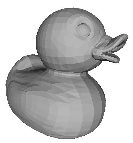
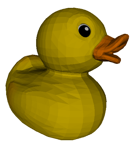
- the model appears more realistic and more detailed, even though it is based on exactly the same triangles
- this is a big reason textures are used heavily, especially in games
- low-polygon count models render fast, and with careful addition of textures, can still look very realistic and detailed
- just as we could apply the same shading equations in both rasterization and in ray tracing, we can also do texture mapping in the same way in each case
- in fact, it is typical to allow the computed texture color
 to be mixed in with the usual ambient, specular, and diffuse colors in the shading equation for a fragment (in rasterization) or a surface point (in ray tracing)
 - the texture color can also modulate another color (more on this below)
- in general APIs that support texturing, like OpenGL, offer many options for using texture colors in the shading computation in different mathematical ways
- at left below is the texture image for the duck, and at right is an overlay of the duck’s triangle mesh onto the texture
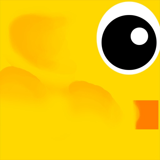
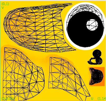
- note that the use of texture coordinates is very flexible, and effectively allows each triangle to be mapped anywhere desired in the texture
- there may even be areas of the texture image that are not mapped to any triangle
- in situations like this it is part of the artist or modeler’s task to create the texture image and to set the
 texture coordinates at every vertex
- though there are some other kinds of uses for textures which automate one or both of those jobs
Interpolating Texture Coordinates
- so we have replaced the literal RGB color values at every vertex with texture coordinates

- but clearly we want the texture to cover an entire triangle, including fragments that are not at the vertices
- again we apply barycentric interpolation
- one simple approach, called affine texture mapping, is just to do the barycentric interpolation in 2D screen space (this is what we have done in other cases)
- if the texture coordinates at the three vertices are
 then the interpolated texture coordinates
  at a pixel whose barycentric coordinates are
  are given by
- this does work and is fast, but the results don’t look quite right when a triangle is viewed at an oblique angle in perspective projection:
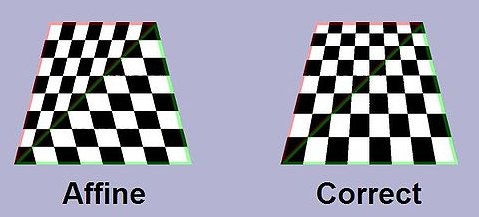
- the solution to this, called perspective correct texture mapping, is a little subtle
- to get perspective projection, we transformed every homogeneous 3D scene point
 by a projective transform to a new point
  , where
  was not necessarily 1
 - we then divided all components of the result by
 to get
- the calculation of
 was then actually based on the resulting coordinates
  and
and 
- it is this division by
 that is causing the problem when trying to interpolate texture coordinates
- recall that it is also possible to define the barycentric coordinates
 for a 3D point on a triangle with 3D vertices
 - if somehow we could get those 3D barycentric coordinates for the fragment that projects to a given pixel, then it turns out that they can be used to correctly interpolate
- i.e. we could correctly say

- but how to get the 3D barycentric coordinates?
- we are already computing the 2D barycentric coordinates
- we can find a mapping from those to the 3D barycentric coordinates
- recall that along the edge from vertex 0 to vertex 1, the 2D barycentric coordinate
 linearly interpolates any vertex attribute
- it also must be the case that
 varies from 0 to 1 along this line segment
 - but due to the perspective division, it turns out that this is not a linear interpolation
- however, the quantity
 , i.e. the 3D
  barycentric coordinate divided by the
  component of the projected but pre-homogenized point does linearly interpolate
 - at vertex 0 this quantity is
 ; at vertex 1 it is
- thus at an arbitrary point along the segment from vertex 0 to vertex 1 it is

- we can solve that for

- a similar derivation gives

- in fact, these equations hold everywhere, not just along the corresponding line segments
- finally, we can calculate

- in these equations, we are calculating the 3D barycentric coordinates corresponding to known 2D barycentric coordinates
- if we do the necessary bookeeping to keep the original
 components of all vertices around after the perspective division, then we have almost all the ingredients we need
 - the only remaining quantity is the interpolated
 value at the current fragment
- we can again use the fact that the quantities
 ,
,  , and
, and  can be interpolated using the 2D barycentric coordinates
  :
: 
- using
 , this simplifies to
Texture Filtering
- once the
 coordinates are known for a given fragment, we need to “look up” the color at that location in the texture image
 - this is another instance of sampling
- in fact, this is typically a resampling operation, because the original texture image is typically a raster, i.e. it is itself a set of samples at some fixed resolution
- the point
 normally will not fall exactly on any single pixel of the texture
 - it is better to consider the correspondence not just between the center of the fragment and the texture (we can consider this to be what is given by just
 ), but a mapping of the entire “little rectangle” of the fragment onto the texture
 - in general, this produces a trapezoid boundary
 (due to perspective projection effects) on the texture; we would essentially like to average a the color of all texture pixels it includes
 - (the computation is again simplified if we ignore the perspective division, at the expense of correct appearance for oblique surfaces; typically anisotropic texture filtering, which effectively uses the more correct trapezoid, is an option that can be turned on for increased quality at the expense of rendering speed)
- how big is
 relative to the texture pixels (texels)?
 - there can be a very large range of variation
- if the camera is very close to the textured surface, or in general if the surface is “zoomed in”, then the texture may need to be arbitrarily magnified
 in this case can be significantly smaller than any texel
- we effectively need to guess a color “between” the original texels
- we can apply the same interpolation techniques as we studied for scaling images, e.g. linear or non-linear interpolation
- on the other hand, if the camera is very far from a textured surface, or in general if the surface is “zoomed out”, then the texture may need to be arbitrarily minified
- here
 can be much larger than one texel
 - it can even be larger than the entire texture image—i.e. the whole texture image must be “shrunk” to a single color value
- the main idea in this case is to collect all the texels included in
 and take their average
 - but note that we need to do this for every fragment
- could be very expensive for a large texture that is significantly minified
- a common approach in practice is to pre-compute a set of shrunk-down versions of the original texture
- these are called mip-maps
- typically each is half the length and half the width of the previous, resulting in a mip-map “pyramid”
- the “mip” is an acronym for the latin phrase “multim in parvo” which means “much in a small space”
- why?
- clearly adding the mipmaps requires more memory storage than just the original texture
- but the largest mipmap requires 1/4 the storage, the second-largest 1/16 of the storage, etc
- the sum of the series
 is only 1/3!
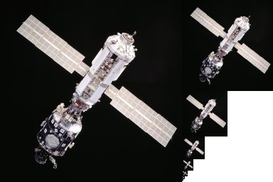
- then the closest matching size is selected to save computation in minification
- still need to interpolate the color value between texels, e.g. by linear interpolation
- doing that both
 (horizontal) and
  (vertical) directions is bilinear interpolation
 - since there are only a fixed set of mip-maps available, there can be a noticeable jump when switching from one to another
- a common option is to smooth such jumps by always finding the two nearest-sized mip-maps, doing bilinear interpolation on each, and then doing a final linear interpolation on the result
- in graphics, this is called “trilinear interpolation”
Multitexturing
- why stop at wrapping a single texture image?
- if we use images that are partially transparent, e.g. with an alpha channel, then it can also make sense to wrap multiple images
- most texturing APIs support this, with a lot of flexibility
- a basic usage might be to map a surface with a basic texture to give its overall appearance, and then add on details in particular regions with other textures
- but it can be more efficient in such cases to just pre-compute (or bake) a single resulting texture
- in general, multi-texturing makes sense mainly when the texture content can vary at run-time
- this is possible and not uncommon in practice
- there was a famous demo in the 1990s by SGI where they mapped the live video feed from a camera onto the surface of a spinning 3D cube
- we will see another example later when we consider shadow mapping
Opacity Mapping, Normal (Bump) Mapping, and Displacement Mapping
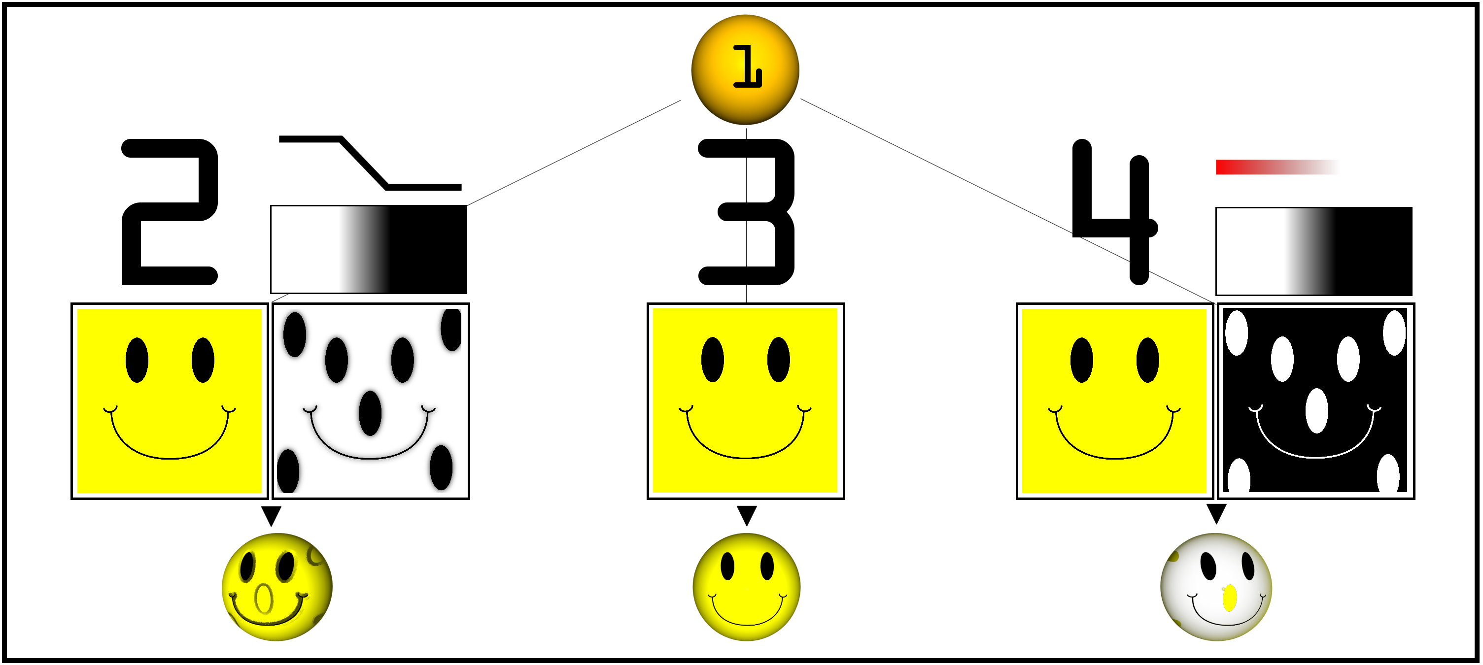
- another simple use of multitexturing is opacity mapping where one of the texture images has only an alpha channel
- this lets the opacity map select which portions of an underlying texture map may “show through”
- the rightmost image below shows an example
- the fact that we have used textures to map to surface colors so far is intuitive, but in theory, we can use the three numbers produced by the texturing process for any purpose
- in practice, there are two common ways to use then besides as RGB color components
- they may be used to set (or modulate (displace)) the surface normal vector
- this can produce the appearance of a slightly bumpy surface, and is hence also called bump mapping
- below left is the original image of a smooth sphere; middle is a bump-map texture; right is the resulting bumpy-looking sphere (another example is in the leftmost part of the smiley face image above)

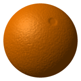
- this is really just a visual trick; the actual geometry of the surface remains the same triangle facets
- some implementations are also capable of actually moving triangle vertices, which is called displacement mapping (image from Wikipedia)
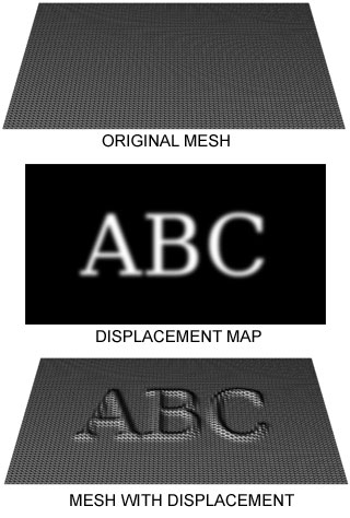
- this is more expensive than normal mapping, but can be more realistic for larger displacements
- for example, the “bumps” that result from normal mapping cannot cast shadows, but those that result from displacement mapping can
Environment Mapping
- recall that some shading effects, specifically mirror reflections and shadows, were easily implemented in ray tracing, but so far we have not seen a way to fit them into the (typically much faster) rasterization framework
- these effects boil down to adjusting the coloration of a surface
- that is exactly what texture maps can do as well, and texture maps are generally supported in rasterization systems
- the only missing piece is to be able to calculate the necessary texture, because in general it is not possible to pre-compute textures that include mirror reflections or shadows
- the appearance of both of these effects depends on the current location of the viewer, the surface, and light sources, all of which may change on-line in many applications
- modern graphics hardware with programmable shaders is offering many opportunities to write programs that do the necessary calculations
- but a simple form of mirror reflection and also a form of shadow computation are possible even without much additional programmability (though some extra support is required for each)
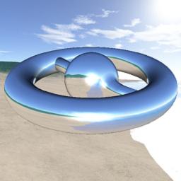
- the idea of environment mapping is to simulate a particular and common mirror-reflection effect: a shiny object that shows a reflection of the background, or the “sky”
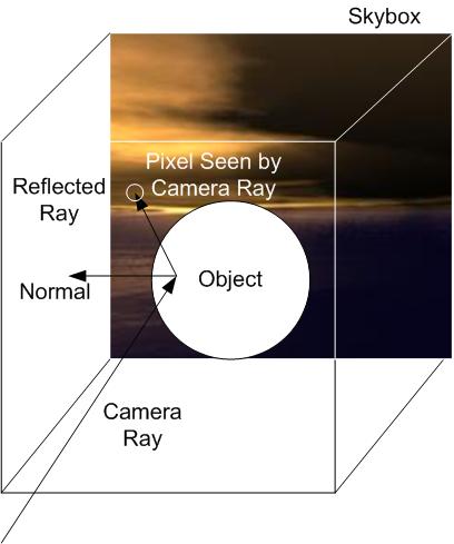
- here, a common approach is to first define a sky box which associates a background image with each of the six faces of a cube that is considered to surround the scene
- these images are sort of like textures, but note that they need not actually be drawn at all, they may just exist for the purpose of calculating the reflection
- then a reflective object is texture mapped in a special mode that calculates texture coordinates based on the current vector from the camera to each 3D fragment location, and the sky box is used as the texel source
- this concept is shown at left below, with an example (using a more interesting shape and a different sky map) to the right
- there are actually two kinds of textures involved in this process:
- the sky box texture itself, which can be one or more raster images loaded from disk
- the texture applied to the shiny object, which is created on the fly as part of the shading calculations
- calculating the shiny texture is done with essentially the same math as we have studied for mirror reflections in ray tracing
- because per-fragment shading computations are normally handled by the implementation of rasterization APIs like OpenGL (which often are actually implemented directly in graphics hardware), an extension is required to the standard shading model
- one OpenGL extension to enable this is EXT_texture_cube_map
- except here, the effect is limited to a “recursion depth” of 1
- and even more seriously, the reflected ray is not “traced”, but rather just is transformed into a lookup of the color on the sky box in the corresponding direction
- thus, the mirror effect does not necessarily include other objects in the scene, unless those objects were included in the sky box images
- finally, how do we get the sky box images in the first place?
- one surprisingly common technique is to just physically take a picture of a round shiny object in reality! (image by Gene Miller)

- a little work in photoshop can then produce a usable sky map
- even though the reflected scene may not be correct, it may still look ok
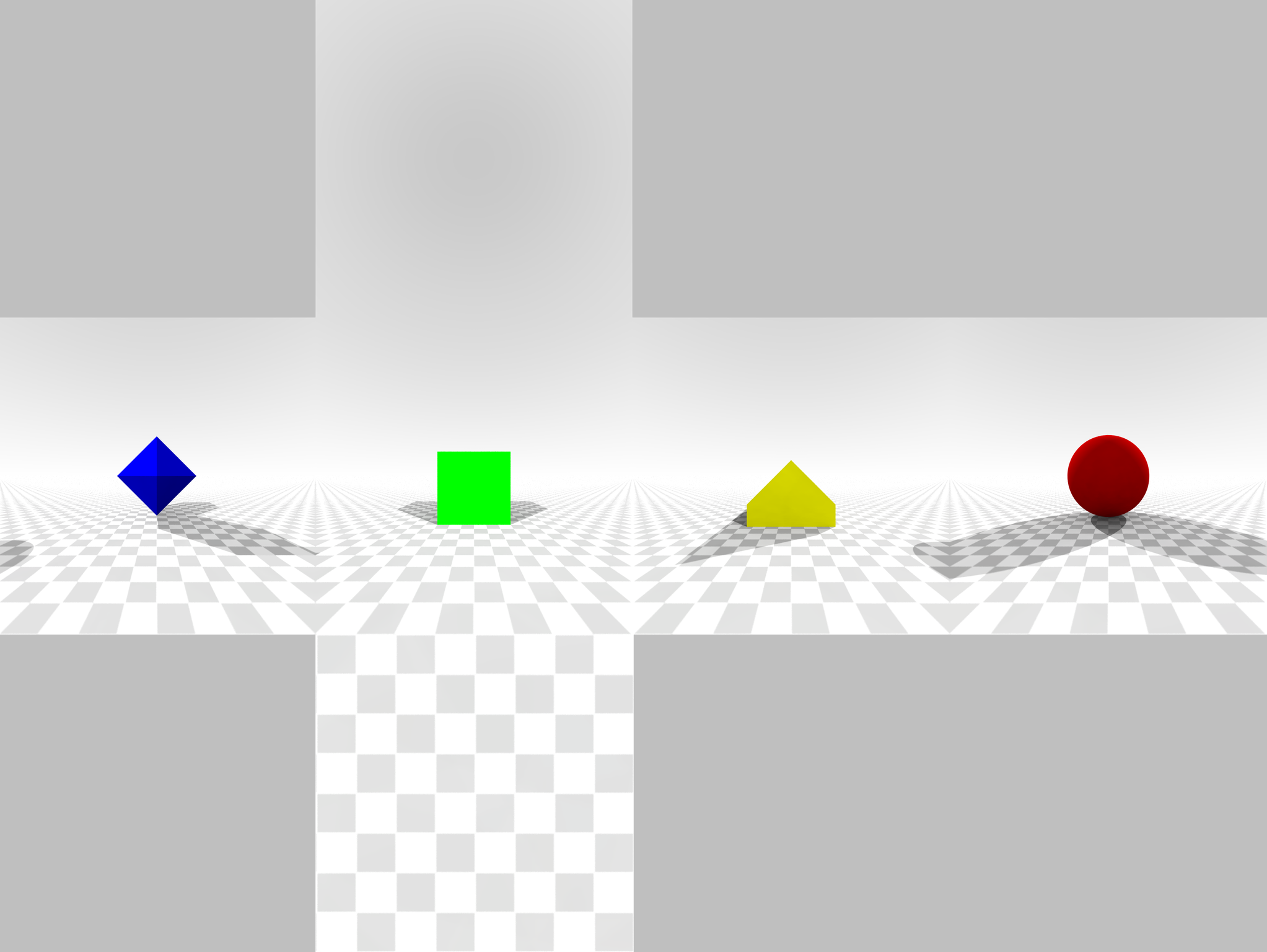
- a more principled and software-only approach is to make renderings of your scene from the perspective of the shiny object
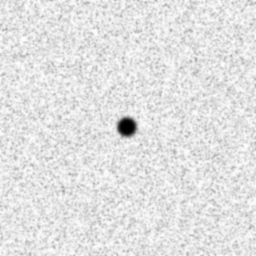
- the left image below shows a scene with a black dot at the center of what will be a reflective object; the right shows that object (a cube) (image from Wikipedia)
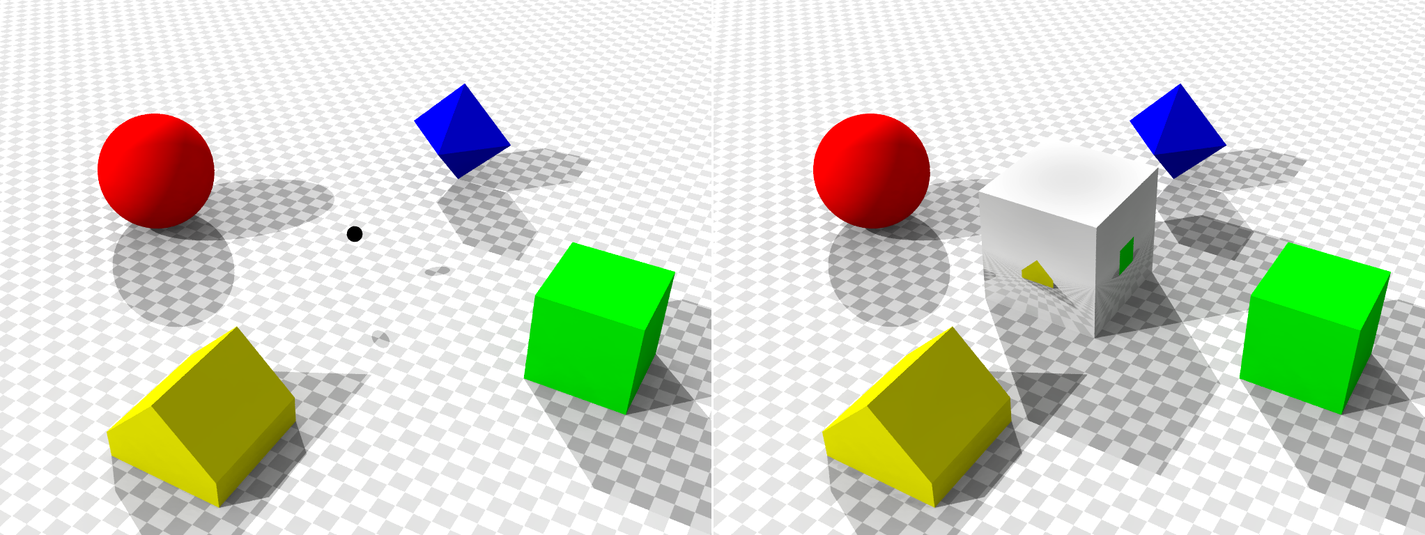
- the sky box images were determined by making renderings of the scene from the point of view of the black dot in four different directions (without the shiny cube itself in the scene):
Shadow Mapping
- a second important light effect that we have implemented in ray tracing, but so far not in rasterization, is the appearance of shadows, where a light source is blocked from hitting some surface by an intervening object
- shadows are effectively a change in the shading of the scene surfaces, and there is a way to implement them using textures
- this process, called shadow mapping, actually ties together several different ideas, including the z-buffer, taking a rendering of a scene from a point of view other than the actual camera (as we did above for calculating sky box images), and a simple extension to the standard shading computations
- a key insight that enables the shadow mapping process is that when the z-buffer technique is used, at the end of rasterization for a frame, the contents of the z-buffer give the z-coordinate of the nearest intersection points for all light rays going from the camera through the image plane pixels
- the remaining ray geometry can be used to determine the other two spatial coordinates
- so in addition to having the color image that would be seen by the camera, we also are left with all the spatial coordinates of the 3D surface points that would be visible to the camera
- the second insight is that, from the point of view of a light source, the surface points that are visible are exactly the points that are not in shadow
- the overall algorithm for shadow mapping (for one light source) has the following steps
- pre-render a view
 of the 3D scene from the point of view of the light source, save only the resulting z-buffer
 - render the frame from the point of view of the camera, as usual
- once the nearest fragment to the camera is determined at a pixel
 , back-compute its 3D spatial coordinates
  (using the ray geometry through
  and the z-buffer value for the fragment)
 - re-project
 into the virtual camera frame that was used to render
  ; this can be accomplished with an appropriate matrix transform, giving
  and the image pixel
  of
of  in
in 
- compare the
 coordinate of
  with the saved z-buffer value
  of
of  in
in  ;
;  is in shadow iff
  is further from the light than
- two common OpenGL extensions used to implement shadow mapping are
- ARB_depth_texture, which supports saving the z-buffer of an image to an off-screen texture map
- ARB_shadow, which supports the reprojection of
 to
to  and the associated depth test in a z-buffer that has been saved as a texture raster
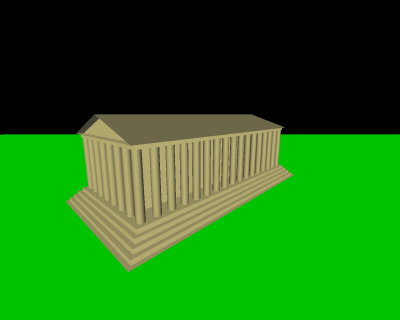
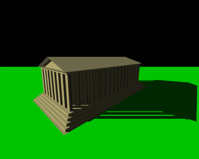
- the image at left below shows a scene with a light source in the upper left, but does not include the shadows that would be cast by the building roof and pillars
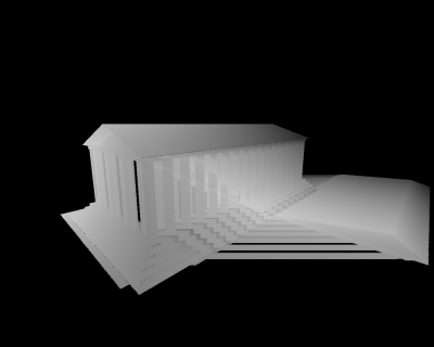
- the second image shows the same scene (actually only the building), rendered from the point of view of the camera; the greyscale intensity corresponds to the z-buffer value
- the third image shows that depth map reprojected onto the scene from the point of view of the camera; this gives a visual depiction of the
 value that will be found for each surface point
- the rightmost image shows the final image including shadows (images from Wikipedia)

Next Time
 in the lower left,
  in the lower right, and
  in the upper left
 texture coordinates at every vertex

 to be mixed in with the usual ambient, specular, and diffuse colors in the shading equation for a fragment (in rasterization) or a surface point (in ray tracing)


