Computer Graphics (CS 4300) 2010S: Lecture 19
Today
- bounding volumes
- picking in 3D
- culling in 3D
- clipping in 3D
Bounding Volumes
- as you know, in 3D graphics it is very common to represent arbitrarily shaped objects as large numbers of small primitives, such as triangles and line segments
- this can produce a good looking rendering, but for complex objects the number of primitives may be very high
- many operations on the shape require time proportional to the number of primitives
- thus, it’s worth considering whether these can be sped up
- one common speed up is to pre-compute bounding volumes, essentially a simpler shape that encloses the actual shape
- the bounding volume is used as a stand-in for the original complex shape in some geometric tests
- such tests can include ray/object picking, object/object intersection or collision, and object/frustum culling
- usually, if such a test returns true, then it is still necessary to re-do the test against all the primitives of the original shape
- however, if the test returns false, then the entire shape can be skipped
- it is often desirable to find small bounding volumes, as they are closer approximations to the original shape, and thus will be less likely to yield a false positive in geometric tests
- common bounding volumes include
- bounding boxes, either axis-aligned or non-aligned
- axis-aligned bounding boxes have their six sides perpendicular to the coordinate frame axes
- non-aligned bounding boxes may be arbitrarily rotated
- they are more complex to compute but can make tighter fits in some cases
- bounding spheres
- bounding ellipsoids (3D generalization of ellipse)
- bounding capsules (cylinder with hemispherical endcaps)
- we will discuss axis-aligned bounding boxes and bounding spheres
- the first question is how to compute the bounding volume given all the primitives making up a shape
- Axis-Aligned Bounding Boxes (AABB)
- an AABB in any number of dimensions (we generally use them in 3D, but they can also be used in 2D) can be defined simply by giving the coordinates of two corners that are opposite each other by a diagonal through the volume of the box
- it is most common to give the coordinates of the “smallest” corner
 (i.e. the coordinate
  is less than or equal to the dimension-
 coordinate of any vertex of any primitive in the object) and the “largest” corner
- to compute these
- initialize
 and
and 
- iterate over all vertices
 of all primitives
- if
 then
then 
- else if
 then
then 
- similar for the
 and
and  dimensions
- bounding spheres
- one method to compute a bounding sphere is to first compute the lower and upper corners
 of an AABB as above
- then the center
 of a bounding sphere is
  , and the radius is
- another method is
- compute the average
 ,
,  , and
, and  coordinate across all vertices of all primitives; call the resulting 3D point
  the center of the bounding sphere
 - compute the distance from every vertex of every primitive to
 ; call the maximum of all the results the radius of the bounding sphere
- however, neither of these approaches are guaranteed to return the tightest bounding sphere
- some slower algorithms which yield tighter, or even optimally tight, spheres are discussed in the book Real Time Rendering by Moller and Haines.
Picking in 3D
- in 2D graphics programs, you are by now very familiar with the concept of picking the user clicks a mouse button, and you must figure out if any graphical object is below that mouse, and if so which one
- in fact, there can be more than one object below the mouse; in that case the user may have intended to pick the topmost one, but they also may want to pick something underneath it (recall the idea of pick drilling)
- picking also makes sense in many 3D graphics programs
- for example, in a 3D game, a user might be able to click on various objects in a 3D world and get information about them
- how to implement the math for picking in 3D?
- one basic idea is to re-use the same series of transforms we developed for projecting objects from their own object coordinates into camera frame
- specifically, recall that if
 is the transform taking object coordinates to world frame and
 is the transform taking world frame to camera frame
- then
 takes object frame to camera frame
- once the object is in camera frame, we can check if it intersects a pick ray that represents the location of the mouse click
- assuming a canvas of
 pixels, with origin in upper left,
  right and
  down, and an
  image plane centered in camera frame at near coordinate
  (note here
  and
and  are the dimensions of the image plane in camera frame length units, and
  and
and  are the dimensions in pixels, which are generally different)
 - for perspective projection, the coordinates of a 3D point
 on the image plane in camera frame corresponding to a click on pixel
  are
are 
- the pick ray is considered to be coincident with the line through the origin of camera frame (also called the eye point) and also through

- the ray starts at
 , and it has direction
- for parallel projection, the math is similar but we also need to factor in the projection scale factor
 :
: 
- also, for parallel projection,

- how to check if an object intersects the pick ray?
- we could simply just check the intersection of the ray with all primitives of the object
- we would need to do this for every object, and those which have at least one intersecting primitive are candidates for the pick
- the final step is to apply whatever resolution method we want to handle the case of multiple objects
- for example, we could just take the one with the nearest intersection to the viewer (i.e. the intersection with maximum
 coordinate in camera frame)
 - though there could still be ties…
- also note that a multiple primitives of a single object can intersect the pick ray
- but this method can be slow because it requires checking every primitive in every object
- if bounding volumes are available, they can be used to speed up the calculations in the common case:
- first check intersection of the pick ray with all bounding volumes; any objects whose bounding volume does not intersect can be ignored in the next step
- for all the objects that did have a bounding volume that intersects the pick ray, check intersection with all the primitives
- note that the worst-case running time of this method is no faster than if bounding volumes were not used
- specifically, this can happen if all bounding volumes happen to be identical in camera frame
- but in practice the use of (reasonably tight) bounding volumes does offer a significant speedup, because objects are often localized to different parts of the spatial scene
- we have already studied how to check if a ray intersects a sphere
- for ray/AABB intersection testing, we could use our ray/plane intersection method, and then check if the resulting intersection points are inside the min and max coordinates of the bounding box
- in practice, faster methods are used; observe that we don’t necessarily need the coordinates of the ray/AABB intersection point, we just need to know whether or not they intersect
- let the ray be defined as a start point
 and a direction vector
  :
: 
- let the AABB be defined by its min and max corners
 and
and  as before
 - the AABB can be considered the intersection of three slabs or slices of space in each dimension
- e.g. one slab would be the space of all points
 with
with 
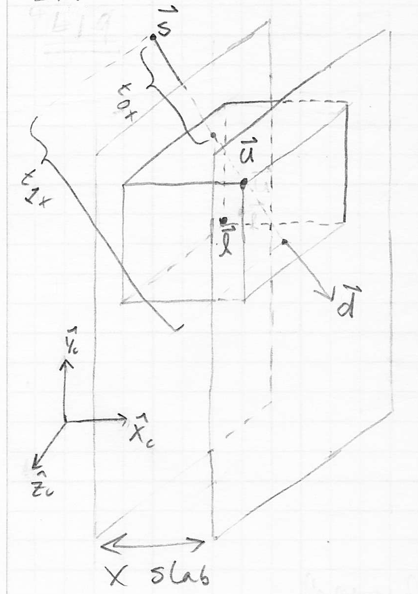
- then we can first find parameter intervals
 for each dimension
  in
in  that correspond to the intersection of the ray with each of the slabs
 - the ray intersects the AABB iff the intersection of these three parameter intervals is not empty
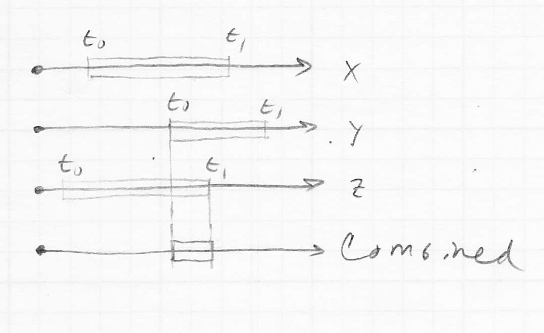
- to solve for the value parameter value
 of the intersection of the ray with the line
  , we only need the
  coordinate from the ray equation:
- solving for
 , we get
- similarly,

- and similar for the
 and
and  dimensions
 - two more details:
- the parameter interval is
 iff the ray is heading in a positive direction, i.e. iff
  ; otherwise the parameter interval is the opposite :
- if
 then floating point division will result in infinity, but if we are careful, this can still be used to give correct results (this requires careful analysis (as presented in Shirley and Marschner, 3rd ed, p. 281); it is one of the reasons that we do the division before the test in the algorithm below)
- putting this all together into an algorithm,
- for each

- let
 ,
, 
- return true iff
 (intersection of the three parameter intervals is not empty) and
  (intersection of the three parameter intervals is not entirely before the start of the ray)
Culling
- as we observed, many operations on an object composed of primitives require iteration across all the primitives
- perhaps the most basic of these is simply rasterizing the object—the basic approach is simply to break that down into rasterizing all the primitives composing the object
- our rasterization methods for primitives are designed to “do the right thing” if the primitive is partially or entirely outside the bounds of the drawing canvas
- but what if an entire object, possibly composed of many primitives, is off-screen; i.e. outside the view volume in 3D?
- our existing approach will work (draw all primitives, but none of them will change any pixels anyway), but we can effectively skip it entirely
- this is called frustum culling
- one basic approach to frustum culling is to use object bounding spheres
- then check the distance from the bounding sphere center to each of the six planes bounding the view volume (we have already studied how to compute the distance from a point to a plane)
- if the distance is greater than the radius of the bounding sphere, the entire object can be culled, without even looking at its primitives
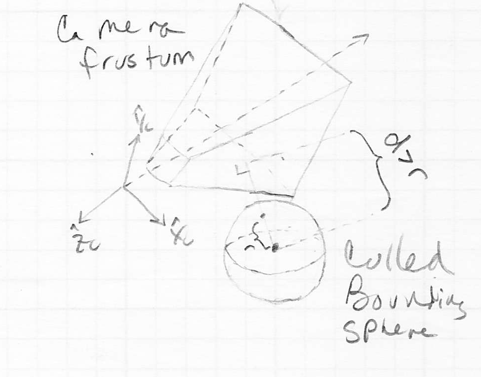
- this is not the only kind of culling; we have already seen a second example in the homework assignments: backface culling
- in many scenes, not only are objects composed of triangle primitives, but also these objects have closed surfaces
- in fact, many objects are like deformations of a sphere
- e.g. the duck model used in the homeworks can be thought of as starting with a sphere and then stretching it like clay (without self-intersection) to “mold” it into the duck shape
- we can always define an inside (back) and an outside (front) face to every triangle on the surface of such a shape
- as we saw in the homeworks, the apparent order of the vertices of each triangle can be used to determine whether we are looking at the front or back face
- because the object is a closed surface, we can never see a backface
- thus any triangle which is currently showing its backface can be culled
- note: backface culling does not use bounding volumes, but we describe it here with the rest of our discussion on culling
- in practice, a third kind of culling, occlusion culling is sometimes implemented
- the basic idea is that there is no need to render an object if it can be more quickly proved that there is some other object in front of, and totally obscuring, it
- there are various approaches to do this, especially in specific applications (such as terrain rendering), but we will not study them in this course
Clipping
- we have studied the view volume, which is in general a frustum (truncated pyramid) in 3D, bounded by the near, far, left, right, top, and bottom planes
- even in the parallel projection case, the view volume can still be considered a frustum, it just happens that in that case the top and bottom of the truncated pyramid are the same size
- we know that only objects (or portions of objects) that are inside the view volume should be rendered to the canvas
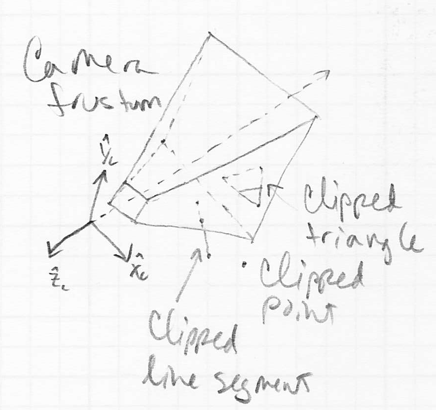
- for objects that are to the left, right, above, or below the view volume, it is possible to handle the required clipping as part of the rasterization step: only fragments with pixel coordinates that actually land in-bounds on the canvas are drawn
- but this is somewhat inefficient, as we could spend a lot of time computing fragments that are out of bounds
- also, this approach simply does not work for objects that are behind the near plane or beyond the far plane (or that are cut by either of those planes)
- in fact this is a major concern; it turns out that the z computations for fragments outside the near-far interval do not work out correctly given the standard projection transforms
- thus it is essential to implement clipping at least for the near and far planes
- the overall idea of clipping is straightforward:
- for each primitive (we will consider both line segments and triangles)
- check if the primitive is totally outside the view volume
- this can be done e.g. by checking if all vertices of the primitive are on the outside of any (note, not necessarily all) of the six bounding planes of the view volume
- if so, the primitive is totally clipped, so skip it entirely
- for each of the six bounding planes

- for each line segment
 bounding the primitive
- check if
 intersects
  ; and if so, shorten it (without changing any of the other bounding segments of the primitive)
 - note that if
 was a side of a triangle, this will change the triangle into a trapezoid
- if the primitive is a triangle that became a trapezoid, split the result into two triangles
- the above computations can be carried out in several different coordinate frames
- modern implementations, such as in OpenGL, typically do all of this at a stage after applying the projective transform but before dividing the results by their fourth coordinate

- it turns out that this gives a little more efficiency
- we will study a simpler case where all the computations are carried out in camera frame (as we have studied for picking and culling above)
- there are three details of the above algorithm that bear some explanation:
- how to determine if a vertex is on the outside of a plane bounding the view volume
- first find an implicit equation for the plane (note that this only needs to be done once at the start of the frame)
- we can calculate the coordinates of the eight vertices of the view volume in camera frame
- let
 be the
  coordinates in camera frame of the left and right planes at their intersection with the near plane
 - let
 be the
  coordinates in camera frame of the top and bottom planes at their intersection with the near plane
 - let
 be the
  coordinates in camera frame of the near and far planes
 - then the four vertices at the near end of the frustum are
 ,
,  ,
,  ,
, 
- for parallel projection, the four vertices at the far end of the frustum are
 ,
,  ,
,  ,
, 
- for perspective projection, the four vertices at the far end of the frustum are
 ,
,  ,
,  ,
, 
- then for each of the six planes, pick any three vertices
- for the near plane, say, use
 ,
,  ,
, 
- an outward pointing normal vector to the plane is
 and
and  is a point on the plane
 - so an implicit equation of the plane is
 or
or  (i.e.
(i.e.  is a point on the plane iff it satisfies this equation)
- finally, a vertex
 is on the outside of the plane iff
- how to “shorten” a line segment that intersects a plane bounding the view volume
- use the same formulation as above to get an implicit equation
 for the plane
 - now form a parametric equation for the line segment from
 to
to  :
:  with
with 
- substitute
 for
for  and solve for
  to get
- the segment intersects the plane iff
 ; if so the intersection point is
- this also implies that exactly one of
 or
or  is inside the plane
 - keep whichever endpoint is already inside, and replace the other one with

- how to split a trapezoid into two triangles
- let the original triangle have vertices
 in order
 - consider the case where
 and
and  are inside the plane, and
  is outside
- this is sufficient without loss of generality, because if a triangle is clipped into a trapezoid by one of the bounding planes, it must be the case that exactly one of the original triangle vertices was outside the plane and the other two were inside
- if the original vertex on the outside was not
 , just temporarily re-number the vertices
- let
 be the intersection point of the segment
  with the plane, and
  be the intersection point of the segment
  with the plane
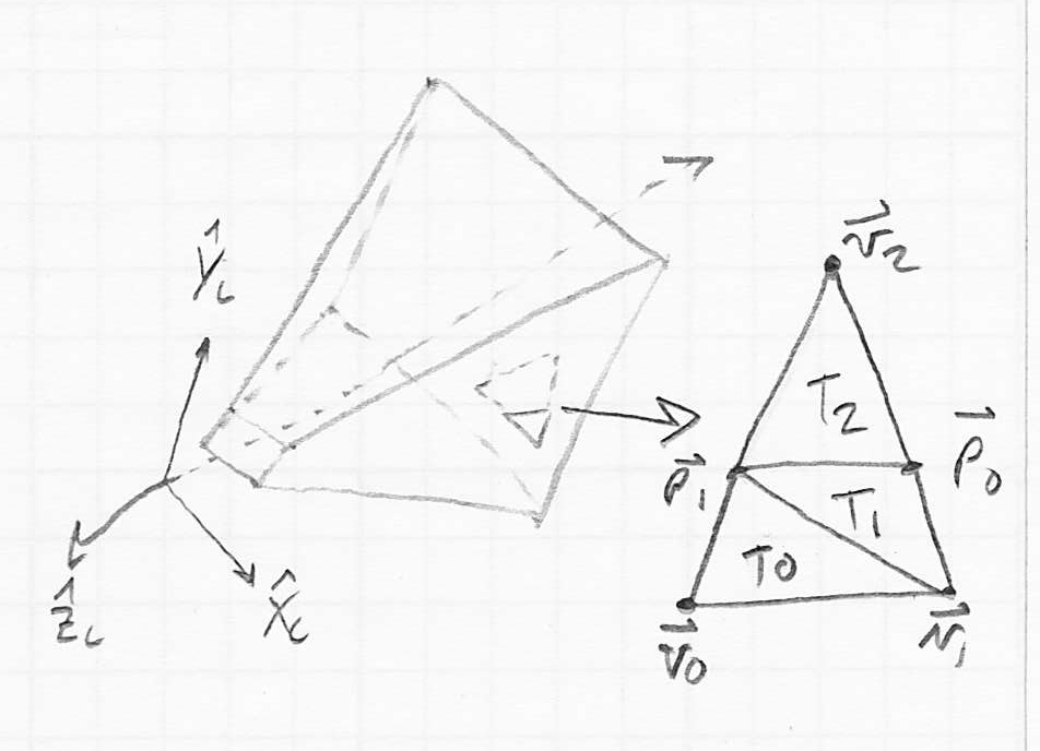
- then the plane can be considered to split the original triangle into three smaller triangles:
 ;
;  ;
; 
 and
and  form the trapezoid that is inside the plane; throw away
Next Time
- lighting, material properties, and surface shading
 (i.e. the coordinate
  is less than or equal to the dimension-
 coordinate of any vertex of any primitive in the object) and the “largest” corner
 and
and 
 of all primitives
 then
then 
 then
then 
 and
and  dimensions
 of an AABB as above
 of a bounding sphere is
  , and the radius is
 ,
,  , and
, and  coordinate across all vertices of all primitives; call the resulting 3D point
  the center of the bounding sphere
 ; call the maximum of all the results the radius of the bounding sphere


