Computer Graphics (CS 4300) 2010S: Lecture 18
Today
- painter’s algorithm for hidden surface removal
- z-buffer data structure for hidden surface removal
- 3D rasterization pipelines
Painter’s Algorithm
- we now have covered two of the four basic steps for rendering 3D scenes
- we know how to transform the vertices of 3D objects into pixel locations on the screen, given the object, camera, projection, and canvas transforms
- we know how to rasterize basic objects (points, line segments, and triangles) given the pixel coordinates of their vertices
- but just doing those two steps will not, in general, result in renderings that look very good, or that are even correct
- a major issue is that we have not yet paid any attention to the issue of occlusion: it is entirely possible for one object to be behind another in 3D
- note, when we say that one thing is behind another, this is by definition evaluated from the current camera viewing direction
- specifically, after transforming two vertices
 and
and  to view coordinates, is behind iff
  (recall that we normally define the camera to be looking down
  )
)
- [the fourth issue is that we have not modeled the effect of light reflecting off the object; we will cover that later in the course]
- so far, we have not checked if one object is behind another in camera frame
- we just rasterize all objects in the order they were specified (which might as well be arbitrary)
- thus, if multiple objects do overlap, the one that is drawn last “wins”, and appears on top of (i.e. in front of) the others
- this suggests a simple solution: just sort the objects from back to front
- this is called the painter’s algorithm, simply because when you physically paint something on top of another painting, it looks like the later one is “in front of” the earlier one
- note that you need to do this sorting based on the camera frame
 coordinates of the objects, which means that you need to re-sort whenever the camera moves (you also need to re-transform the objects in such a case anyway)
- if your objects can move around relative to each other within the scene, re-sorting is required in that case as well
- you probably also know that (unless you are willing to enforce a strict upper bound on the total number of objects), you cannot sort
 objects faster than
- this is a big deal because up to this point the transformation of all objects into camera frame was an
 process
 - i.e. the added depth sort becomes the most expensive part of the transformation process (a bottleneck)
- this does matter in practice as scenes can easily have hundreds of thousands or even millions of triangles
- in this discussion, when we say “object”, we mean one of the geometric primitives in the scene: point, line segment, or triangle
- what is the “ coordinate” of such an object?
- there is no ambiguity if the object is just a point, of course
- but for a line segment or a triangle, the general case is that the object will actually occupy a range of coordinates in camera frame
- which to use?
- one approach is to find the maximum coordinate of all the vertices in the object (this will be the nearest vertex in that object to the camera), and call that the object’s coordinate
- the painter’s algorithm is easy to implement
- it has the disadvantage of becoming a bottleneck in the transformation stage for large scenes
- however, it has other problems
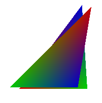
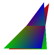
- first, observe that it doesn’t work for intersecting triangles: there is just no way to paint one before the other which looks correct
- the right image below shows a correct rendering of two intersecting triangles; the image on the left shows a typical result of trying to apply the painter’s algorithm in such a case
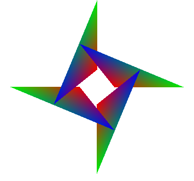
- second, even if there are no intersecting triangles, it is still possible to have an occlusion cycle, and the painter’s algorithm can neither handle this
- the right image below shows a correct rendering of four triangles in an occlusion cycle; the image on the left shows a typical result of trying to apply the painter’s algorithm in such a case

- one solution to both of these problems is to devise a way to split up primitives that have such problems into smaller pieces that neither intersect nor have overlap cycles
- this is possible, but pretty tricky to implement in a way that’s both correct and fast
- for that reason, the painter’s algorithm is not used very much
- it is not typically directly implemented by 3D graphics libraries such as OpenGL
- instead, another method called Z buffering is used, which we will look at in a moment
- even so, there is still sometimes a need to implement the painter’s algorithm
- one common situation is when trying to handle overlapping translucent objects
- this is commonly implemented using alpha blending, as we have already seen
- the z-buffering method does not work correctly for translucent objects
- the painter’s algorithm does have the above issues, but applying it to translucent objects still works better than nothing (and you can still use the z buffer for opaque objects in a mixed scene)
Z-Buffer
- we have already observed that we can fix the problems with the painter’s algorithm by splitting up problem primitives into smaller pieces
- for example, two overlapping triangles can be split at their intersection line into four smaller triangles which do not overlap
- it is generally hard to figure out how to do such splitting well, unless we take the perspective of simply splitting up every primitive into the smallest possible primitives
- but in fact, we already are doing that!
- the rasterization step effectively splits a line segment or triangle into a bunch of pixels
- these are effectively the smallest fragments we need to care about
- the idea of the buffer begins with this observation: instead of sorting the big primitives (lines and triangles) as indivisible objects, move the sorting step to operate only on the pixel-sized fragments that are generated during rasterization of such primitives
- one way to do this (this is not the z-buffer technique, but leads up to it) would be to store a list for every pixel on the canvas
- yes,
 lists for a canvas that is
  pixels wide and
  pixels tall
 - at the beginning of a frame, clear all lists
- during rasterization, whenever a fragment is generated (i.e. for a pixel that is inside some point, line segment or triangle), store it in the list for the corresponding pixel
- also store with each fragment its interpolated camera frame coordinate
- coordinates for fragments can be interpolated from the coordinates of the primitives vertices in exactly the same way as other data (such as color)
- for a triangle, just use barycentric interpolation on the three vertices’ coordinates
- finally, after all primitives have been rasterized, sort all the lists in order of decreasing fragment , and only keep the front-most fragment for each pixel
- this of course would be a pretty expensive algorithm, both in terms of computation time and required memory
- observe that the final result is just the nearest fragment to the viewer for each pixel—all other fragments for that pixel are just thrown away
- we thus don’t need to store all fragments for a pixel, just the nearest one that has been produced so far
- we can do the necessary bookkeeping without any sorting
- we just need one more array in memory, called the z-buffer
- at the beginning of the frame, initialize all entries in this array to

- whenever a fragment is generated, compare its interpolated camera frame coordinate
 to the value
  currently in the array, which is the coordinate of the nearest fragment that has been generated so far for that pixel
 - if
 then the new fragment is not nearest, so just throw it out and move on
 - otherwise, update
 and draw the fragment onto the canvas (in this context, we can call the canvas the “color buffer”, to emphasize that we now have multiple buffers holding different kinds of data (depth, color) for each pixel)
- the z-buffer works well; because it effectively sorts (well, at least finds the nearest) the smallest effective pieces, it does not suffer from the issues that the basic painter’s algorithm has with intersecting or cyclically overlapping primitives
- also, because it avoids sorting, it does not introduce any bottleneck
- the main cost of the z-buffer approach is that an additional array of memory is needed
- in modern computers this is not really a big deal
- however, because the z-buffer must be involved in the inner loop of rasterization for every primitive, if the process of rasterization is going to be accelerated by specialized hardware, then it also is generally necessary to put the z-buffer itself on that hardware
- in fact, a very fast type of memory is used to implement the z-buffer in such hardware
- this memory is relatively expensive, so there is a cost trade-off vs the number of bits
 allocated per pixel in the z-buffer
 - a common choice is
 , which yields (only)
  z “bins”
 - think of these bins as slices of the view volume, perpendicular to the camera frame
 -axis, stacked like slices of bread between the near and far planes of the view volume
 - observe that since there are a fixed number of these slices, increasing the distance between the near and far planes actually increases the width of each z-buffer bin
- for parallel projection, the bin size is effectively

- for perspective projection, the bin size actually depends on the distance from the viewer
- for an object at camera frame coordinate
 , the bin size is approximately
  (derivation in Shirley & Marschner, 3rd Ed., p. 177)
 - so the nearest bin is smallest, and the bin size increases quadratically with the distance
 from the viewer
 - the largest bin will thus be at
 , with size
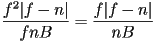
- that fragments with interpolated camera frame coordinates that differ by less than the bin size are not guaranteed to be sorted correctly
- in practice, this is a detail that does require attention
- there is now a trade-off in setting your near and far planes:
- the closer together you put them, the better the discrimination of the z-buffer (because the smaller the z-bins)
- but that also reduces the view volume, and recall that only the parts of objects that are inside the view volume are rendered at all
- for the case of perspective projection, reasoning about the maximum bin size also shows that there is a preference for the largest possible
 and the smallest possible
  , which again suggests minimizing
  , but also that the whole view volume should be pushed “away” from the viewer; this must be balanced by other practical considerations (typically this interacts with the effective field of view)
The 3D Rasterization Pipeline
- the four steps we discussed at the beginning of today’s lecture are a very common way to structure 3D rasterization pipelines in practice
- vertex processing—takes in the object vertices (and optionally also surface normal vectors), applies the object-to-world transform, followed by the the camera, projection, and canvas transforms
- rasterization—generates fragments for each primitive
- shading—adjusts fragment colors to simulate the effect of lighting; also images can be painted onto surfaces at this stage, which is called texture mapping (we will discuss this in detail later)
- blending—finally, the fragments are combined in some way to produce the colored pixels in the final image; one of the most basic methods is to just apply the z-buffer algorithm to keep only the nearest fragment at each pixel
- such a “pipeline” can be thought of as taking in a collection of primitives, passing the primitives through four corresponding stages of computation, and finally producing an image of the scene (i.e. one frame in an animation)
- this can all be implemented in software, either in your own code, or using an existing software rasterization library, such as Mesa 3D
- however, it is currently common to add specialized hardware to computers, called a Graphics Processing Unit (GPU), that assists in some or all stages of the pipeline
- this helps handle larger scenes at faster framerates, and for that reason GPU hardware is very popular to increase the performance of 3D games
- two currently common manufacturers of such hardware are NVidia and ATI
Next Time
- picking, culling, and clipping in 3D