Computer Graphics (CS 4300) 2010S: Lecture 17
Today
- camera transformation and navigating in 3D
- the image plane
- parallel projection
- perspective projection
- projective transformation
- the view volume
- transforming view volume coordinates to canvas pixels
- in 2D, we mentioned the idea of navigation
- recall that a graphical scene with various parts can be represented as a scene graph, i.e. a tree where
- the nodes are objects to draw
- the edges are coordinate transforms from each object to its parent
- the root of the tree is the “world frame”
- by inserting an extra transform just above the root, we could move the whole scene around
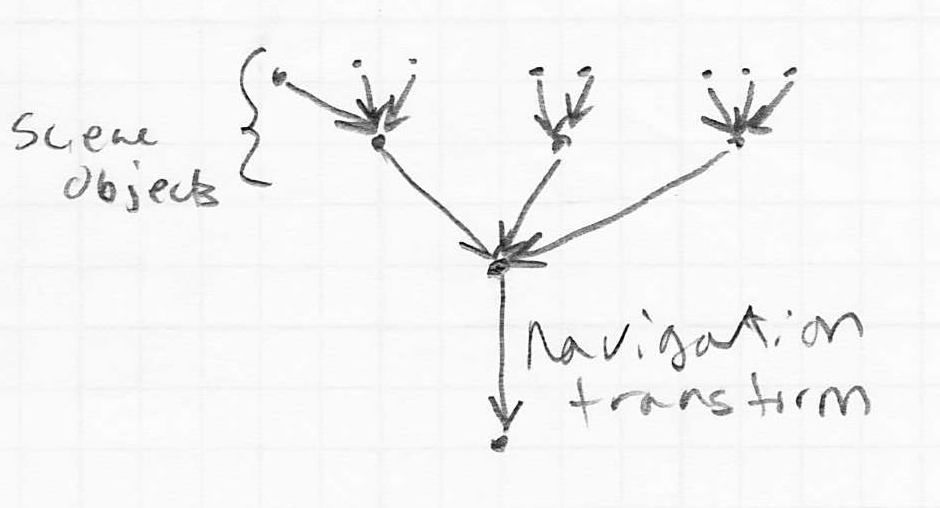
- in 3D the same setup can be used, however, it is more common to consider the camera to be just another object in the scene graph
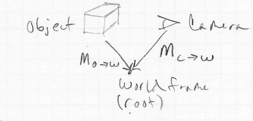
- the local-to-world transform (i.e. the composite model transform) for the camera is

- typically this is a rigid-body transform (rotation and translation only)
- think of it like carrying a camcorder
- modifying
 moves the camera around in the scene, i.e., navigates
- if the local-to-world transform for some particular object we want to draw is

- then the transform that takes the object to camera frame coordinates is

- if we define shorter symbols
 and
and  , then we can just write
- we can call this the camera transformation for object

- applying the camera transformation generally makes the process of rendering
 as it would appear in the camera much easier
The Image Plane
- once all objects have been transformed to camera frame, we still need to decide to which pixels they actually rasterize
- typically, cameras cannot see behind themselves
- also, cameras typically have a limited field of view (i.e. side to side and up and down)
- putting these constraints together implies that only a sub-volume of the full camera coordinate frame is actually mapped to the canvas
- in fact, we can define
- the camera viewing direction as a vector in camera frame, typically this is set by convention to

- an image plane perpendicular to the camera viewing direction at some signed distance
 from the origin of the camera frame
 - left, right, top, and bottom coordinates in the image plane that map to the sides of the canvas
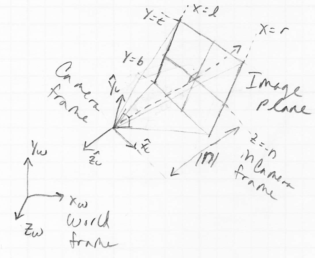
- we can think of each point on the object as projecting a ray through the image plane
- in a moment, we will consider two different ways to construct such rays
- if the intersection point of the ray and the image plane is inside the rectangle defined by the left, right, top, and bottom coordinates, then not only is that point in view (though it may be blocked by some other part of the object that is nearer to the camera), we also are only a scale factor away from having its exact pixel coordinates
- note: points with camera frame
 coordinate greater than
  are considered behind the camera, and are not rendered
Parallel Projection
- typically we consider the image of a set of train tracks (parallel lines in 3D space) that recede into the distance to actually appear as if the tracks converge
- this is called perspective projection; we will study it later
- but first consider a simpler case where such an image also shows parallel lines for the tracks
- this is called parallel projection
- images like this are produced by constructing rays from object points through the image plane, such that the rays are parallel to the camera frame
 axis
axis
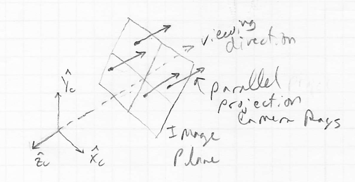
- when we do this, the
 coordinates of the intersection of the ray and the image plane in camera frame coordinates are simply the original
  coordinates of the point on the object
- we simply drop the
 coordinate of the original point in 3D
- the resulting images generally look ok, except that they do not have the typical depth cue that we are used to seeing, that objects further away appear smaller than nearby objects, even if the actual object sizes are the same
- parallel projection is often used in scientific imaging applications and in CAD
Perspective Projection
- parallel projection is simple to implement but does not always yield very convincing images
- fortunately, it is also fairly simple to implement correct perspective projection, where train tracks that go off into the distance actually appear to converge
- the main idea is to change how we construct the ray from an object point
- instead of having such rays be parallel to the camera frame
 axis, we now have them intersect the camera frame origin
 - that’s it!
- but now the task of computing the
 coordinates of the intersection of such a ray with the image plane takes a little more math
 - we can derive the math for a single coordinate—we’ll do
 ; it turns out the same pattern also applies to
- let the coordinates of the 3D point
 in camera frame be
- then the ray from
 through the camera frame origin defines two right triangles
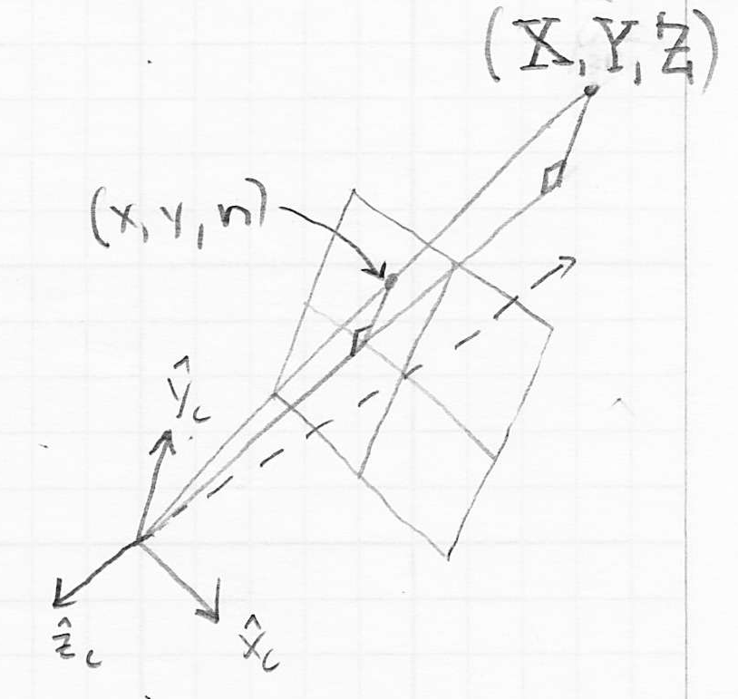
- these are similar triangles because they have the same angles
- thus, the following relationship holds:

- solving for
 :
: 
- the case for
 is similar:
  :
: 
- note that the process of projection onto the image plane, whether in the parallel or perspective case, is essentially the transformation of 3D scene points onto the 2D image plane
- in fact, as for the coordinate transformations we have already seen, it is possible to implement this process by multiplying a homogeneous representation of
 by a
by a  projection matrix
 - for the case of parallel projection, the projection matrix just zeros the
 coordinate
- we can sneak in a scale factor
 to make the image look larger (
 ) or smaller (
 )
) 
- so we could say that the image point

- but it is not so easy to do the same for perspective projection
- there is no way to get the needed division by
 using just matrix multiplication
 - the commonly used solution to this conundrum is to
- allow the fourth coordinate of a point (sometimes this is called the
 coordinate) to be different from 1
 - use the bottom row of the transformation matrix to calculate this
 based on the coordinates of the input point
 - divide the resulting point by its
 coordinate in a final added step (note that this returns its
  coordinate to 1)
- if we do all of that, then we can use the following as a perspective transformation matrix:

- and we could say that the image point

- finally, we can combine all the transformations we have so far (using
 as either
  or
or  , as desired): for every 3D point in object
  apply the combined transform
- i.e. first transform from
 ’s local coordinate frame to world frame (
 )
) - then transform from world frame to camera frame (
 )
) - finally transform from camera frame to the image plane (
 )
)
The View Volume
- the above projection transforms computed the
 coordinate of the image point
  as 0, intentionally
 - but for the purposes of figuring out which object points appear in front of others, it is useful to also “keep the
 coordinate around”
 - it is easy to fix this for parallel projection, just use

- but it is trickier to do this for perspective projection
- the commonly used approach is to define a far plane parallel to the image plane, but with view-frame
 coordinate
  (i.e.
(i.e.  is further away from the camera than
  , and both are negative)
- just as points closer to the camera than the image plane or near plane at
 are not rendered, points farther away than the far plane are neither rendered
 - this effectively encloses the view volume by six planes, often called the near, far, left, top, right, and bottom planes (image copyright SGI; note that in this image “Horizontal FOV” and “Vertical FOV” are actually angles; FOV stands for Field Of View)
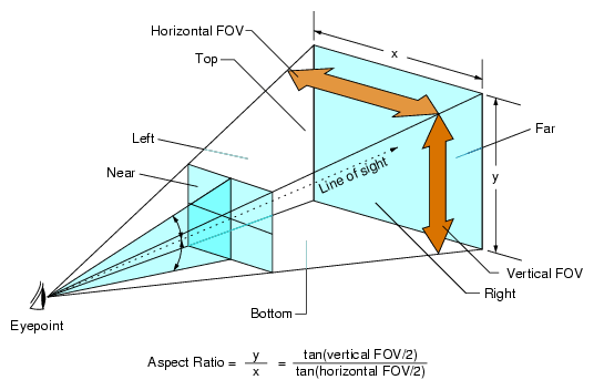
- this kind of truncated pyramid shape is called a frustum
- we can now define

- the effect is to that now

- it is probably difficult to understand why we would set up the
 coordinate of
  in such a seemingly odd way
 - the reason is that by doing it this way
- while we have presented the view volume only for the case of perspective projection, it turns out that many common 3D rendering libraries, such as OpenGL, always define a view volume with six bounding planes, even for parallel projection
- the reasons have to do with the way z buffering is implemented, as we will see later in the course
- so far we have ignored the physical units (i.e. the scale) of points in the image plane
- in practice, we often need to align a canvas with say
 pixels, with the rectangle in the image plane defined by the left, right, bottom, and top boundaries
 - also, often we have
 right and
  down on the canvas, and the origin of the canvas in the upper left
 - we can use yet another matrix to apply a final transformation that takes image plane points
 to actual pixel units
 - for simplicity, here we consider the case where
- in this case, we can define

- and the overall transformation from object frame coordinates all the way to canvas pixels is

Next Time
- hidden surface removal
- 3D rasterization hardware


 moves the camera around in the scene, i.e., navigates


